Airlink APO1000 User Manual
Airlink APO1000 Manual
 |
View all Airlink APO1000 manuals
Add to My Manuals
Save this manual to your list of manuals |
Airlink APO1000 manual content summary:
- Airlink APO1000 | User Manual - Page 1
Wireless G 2.4GHz 500mW Outdoor AP Model: APO1000/APO1010 User's Manual V.1.0 - Airlink APO1000 | User Manual - Page 2
...12 2.1.1 Package Contents ...12 2.1.2 Panel Function Descriptions ...13 2.1.3 Hardware Installation Steps ...15 2.2 WEB MANAGEMENT INTERFACE INSTRUCTIONS 16 CHAPTER 3. AP MODE CONFIGURATION...18 3.1 EXTERNAL NETWORK CONNECTION ...18 3.1.1 Network Requirement ...18 3.1.2 Configure LAN IP - Airlink APO1000 | User Manual - Page 3
4.3.5 Backup / Restore and Reset to Factory 69 4.3.6 Firmware Upgrade...70 4.3.7 Network Utility ...71 4.3.8 Reboot...72 4.4 SYSTEM STATUS...73 4.4.1 System Overview...73 4.4.2 WDS Link Status...75 4.4.3 Extra Information ...76 4.4.4 Event Log...78 CHAPTER 5. CPE MODE CONFIGURATION...79 5.1 - Airlink APO1000 | User Manual - Page 4
...147 6.5.4 Extra Information ...148 6.5.5 Event Log...150 CHAPTER 7. COMMAND LINE INTERFACE(CLI 151 7.1 ACCESSING THE CLI WITH TELNET ...151 7.2 USING THE CLI ...152 APPENDIX A. WINDOWS TCP/IP SETTINGS...154 APPENDIX B. WEB GUI VALID CHARACTERS 156 APPENDIX C. NETWORK MANAGER PRIVILEGES 160 - Airlink APO1000 | User Manual - Page 5
4 - Airlink APO1000 | User Manual - Page 6
Internet Service Provider's (WISP) outdoor network via wireless or wired bridge to access to Internet The die-cast sealed APO1000/APO1010 wireless Access Point 2. Repeater: To expand wireless service by repeating prior AP 3. WDS : It can be used to expand Ethernet network via wireless WDS Link 4. - Airlink APO1000 | User Manual - Page 7
1.2 System Concept The APO1000/APO1010 is not only designed and used as traditional outdoor AP, but also with rich features tailored for WISP applications. The two . 5. Wireless coverage for indoor and outdoor grounds in private resorts, home yards, or gulf course communities. APO1000/ APO1010 2 - Airlink APO1000 | User Manual - Page 8
1.3 Applications in Wireless Network APO1000/APO1010 is a multiple mode system which can be configured either as a wireless gateway or an access point as desired. It also can be used as WDS link for Ethernet network expansion. This section depicts different applications in AP Mode, WDS Mode, and CPE - Airlink APO1000 | User Manual - Page 9
APO1000/APO1010 APO1000/APO1010 „ Configuration in WDS Mode (Pure WDS) An access point can be either a wireless clients and pass data upwards to a network wirelessly. In this mode, it can support single or multiple WDS links and no wireless clients can associate with it though. Î Example 1 : Point- - Airlink APO1000 | User Manual - Page 10
APO1000/APO1010 5 - Airlink APO1000 | User Manual - Page 11
in CPE Mode It can be used as an Outdoor Customer Premises Equipment (CPE) to receive wireless signal over last mile application, helping WISPs deliver wireless broadband Internet service to residents and business customers. In the CPE mode, APO1000/APO1010 is a gateway enabled with NAT - Airlink APO1000 | User Manual - Page 12
+ Universal Repeater Mode It can be used as an Client Bridge + Universal Repeater to receive wireless signal over last mile applications, helping WISPs deliver wireless broadband Internet service to new residential and business customers. In this mode, APO1000/APO1010 is enabled with DHCP Server - Airlink APO1000 | User Manual - Page 13
create multiple subscriber service tier using per-subscriber rate limiting features, and manage centrally. APO1000/APO1010 outdoor bridge the subscriber with an Ethernet connection for a local access. APO1000/APO1010 outdoor high power Bridge supports four operational modes, the AP mode, the WDS mode - Airlink APO1000 | User Manual - Page 14
an IEEE802.11 network. 9 It allows a wireless network to be expanded using multiple access point without the need for a wired backbone to link them. and PPPoE on WiFi WAN Connection Î Support PPTP/L2TP/IP Sec Pass Through Î PPPoE Reconnect - Always On , On demand, Manual Î MAC Cloning Î DHCP Server Î - Airlink APO1000 | User Manual - Page 15
MAC Filter Î Support IP Filter Î Bandwidth traffic Shaping 7. Wireless Feature Î Transmission power control : 9 Levels Î Channel selection : Manual or Auto Î No of associated clients per AP : 32 Î Setting for max no associated clients : Yes Î No. of ESSID (Virtual AP) : 8 Î No. of Max. WDS - Airlink APO1000 | User Manual - Page 16
Î No. of registered RADIUS servers : 2 Î VLAN assignment on BSSID Î Support VLAN tag over WDS „ Quality of Service Î DiffServ/ ToS Î IEEE802.1p/ CoS Î IEEE 802.1Q Tag VLAN priority control Î IEEE802.11e WMM „ System Administration Î Intuitive Web Management Interface Î Password Protected Access Î - Airlink APO1000 | User Manual - Page 17
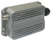
2.1.1 Package Contents The standard package contents of APO1000/APO1010: „ APO1000/APO1010 x 1 „ Quick Installation Guide x 1 „ CD-ROM (with User Manual and QIG) x 1 „ PSE with AC Cable x 1 „ Mounting Kit x 1 It is highly recommended to use all the supplies in the package instead of - Airlink APO1000 | User Manual - Page 18
2.1.2 Panel Function Descriptions ¾ APO1000 Front Panel Rear Panel 1. Reset Button : System reboot button press until LED flashed and release for system reboot or for reset to factory default press, - Airlink APO1000 | User Manual - Page 19
¾ APO1010 Front Panel Rear Panel 1. Reset Button : 2. Power : 3. Signal Strength : 4. Signal Strength : 5. Signal Strength : 6. WLAN : 7. Ethernet : 8. PoE Connector : System reboot button press until LED flashed and release for system reboot or for reset to factory default press, LED flashes - Airlink APO1000 | User Manual - Page 20
an Ethernet cable to the Power Injector and the other end to a computer. Î Source power to Power Injector in order to supply power to APO1000. ¾ APO1010 Front Panel Rear Panel Î Connect Power Injector to the PoE connector on the front panel. Î Connect an Ethernet cable to the Power Injector - Airlink APO1000 | User Manual - Page 21
2.2 Web Management Interface Instructions APO1000/APO1010 supports web-based configuration. Upon the completion of hardware installation, APO1000/APO1010 can be configured through a COMPUTER by using its web browser such as Internet Explorer or Mozilla Firefox. 1. Default IP Address : 192.168.2. - Airlink APO1000 | User Manual - Page 22
The network manager Login Page then appears. Enter "root" for user name and "default" for password, and then click OK to login to the system; the root manager account is used as an example here. „ Login Success System Overview page will appear after successful login. 17 - Airlink APO1000 | User Manual - Page 23
System Overview Clients WDS List Extra Info Event Log Table 3-1: AP Mode Functions 3.1 External Network Connection 3.1.1 Network Requirement Normally, APO1000/APO1010 connects to a wired LAN and provides a wireless connection point to associate with wireless client as shown in Figure 3-1. Then - Airlink APO1000 | User Manual - Page 24
instructions to setup the local IP Address and Netmask. Please click on System -> LAN and follow the below setting. „ Mode : Check either "Static IP" or "Dynamic IP" button as desired to set up the system IP of LAN port . Î Static IP : The administrator can manually when the APO1000/APO1010 is - Airlink APO1000 | User Manual - Page 25
APO1000/APO1010 APO1000/APO1010 Click Save button to save your changes. Click Reboot button to activate your changes 20 - Airlink APO1000 | User Manual - Page 26
3.2.1 Wireless General Setup The administrator can change the data transmission, channel and output power settings for the system. Please click for your environment. If you are not sure from which setting to choose, then use the default LEVEL 9 setting. Click Save button to save your changes. Click - Airlink APO1000 | User Manual - Page 27
ACK Timeout : ACK timeout is in the range of 1~372 and set in unit of microsecond. The default value is 48 microsecond. All data transmission in 802.11b/g request an "Acknowledgement" (ACK) send by receiving radio. The transmitter will resend the original packet if correspondent ACK failed to arrive - Airlink APO1000 | User Manual - Page 28
to turn on RTS. CTS Timeout will take effect only when RTS is turned on. Unlike wired Ethernet, radio transmission may begin with a RTS (Request to Send) as SSID, channel, encryption keys, signal strength, time stamp, support data rate. All the radio stations received beacon recognizes the existence - Airlink APO1000 | User Manual - Page 29
is defined as Delivery Traffic Indication Message. It is used to notify the wireless stations, which support power saving mode, when to wake up to receive .11b peers, and disabling it will save transmission time used by RTS/CTS. RTS/CTS threshold is effective only when 802.11g protection mode is made - Airlink APO1000 | User Manual - Page 30
3.2.3 Create Virtual AP(VAP) The APO1000/APO1010 support broadcasting multiple SSIDs, allowing the creation of Virtual The VAP0 always On „ Security Type : Indicate an used security type of the respective Virtual AP „ MAC Filter : Indicate an used MAC filter of the respective Virtual AP „ MAC Filter - Airlink APO1000 | User Manual - Page 31
of client associations, security type settings. Click Edit button on the VAP Edit column, and then a Virtual AP setup page appears. „ ESSID : Extended Service Set ID, When clients are browsing for available wireless networks, this is the SSID that will appear in the list. ESSID will determine the - Airlink APO1000 | User Manual - Page 32
Support : By default, it's "Disable". Inter Access-Point Protocol is designed to enforce unique association throughout an ESS(Extended Service Open system and Shared. 9 Key Index : key index is used to designate the WEP key during data transmission. 4 different WEP keys can be entered at the same - Airlink APO1000 | User Manual - Page 33
32 characters ASCII 5 characters 13 characters 16 characters Î WPA-PSK/WPA2-PSK : WPA or WPA2 Algorithms enable the system to access the network by using the WPA-PSK protected access. 9 Cipher Suite : By default, it is TKIP. Select either AES or TKIP cipher suites 9 Group Key Update Period : By - Airlink APO1000 | User Manual - Page 34
of the Authentication RADIUS server. • Port : By default, it's 1812. The port number used to communicate with RADIUS server. • Shared secret : A secret key used between system and RADIUS server. Supports 1 to 64 characters. • Accounting Server : Enable or Disable accounting features in RADIUS server - Airlink APO1000 | User Manual - Page 35
of the Authentication RADIUS server. • Port : By default, it's 1812. The port number used to communicate with RADIUS server. • Shared secret : A secret key used between system and RADIUS server. Supports 1 to 64 characters. • Accounting Server : Enable or Disable accounting features in RADIUS server - Airlink APO1000 | User Manual - Page 36
of the Accounting RADIUS server. • Port : By default, it's 1813. The port number used to communicate with RADIUS server. • Shared Secret : A secret key used between system and Accounting RADIUS server. Supports 1 to 64 characters. Click Save button to save your changes. Click Reboot button to - Airlink APO1000 | User Manual - Page 37
a maximum of 20 clients allowed in this MAC Filter List. The MAC addresses of the wireless clients can be added and removed to the list using the Add and Delete buttons. Click Reboot button to activate your changes MAC Access Control is the weakest security approach. WPA or WPA2 security method - Airlink APO1000 | User Manual - Page 38
links. A WDS link is bidirectional and both side must support WDS. Access points know each other by MAC Multiple Points with different VLAN settings APO1000/APO1010 Figure 3-3 Point to Multiple on the wired Ethernet port. Ensure to match VLAN ID used on the network of the peer. WDS link won't carry - Airlink APO1000 | User Manual - Page 39
Open system and Shared. 9 Key Index : key index is used to designate the WEP key during data transmission. 4 different WEP keys can be entered at the same time, but only one is chosen. 9 WEP Key # : Enter HEX or ASCII format WEP key value; the system supports up to 4 sets of WEP keys. 34 - Airlink APO1000 | User Manual - Page 40
Peer's MAC Address : Enter the MAC address of WDS peer. Î VLAN ID : By default, it's disabled(space) with no VLAN ID. When desired, this system supports tagged VLAN from 0 to 4094. Î Description : Description of WDS link. The WDS link needs to be set at same Channel and with same Security Type - Airlink APO1000 | User Manual - Page 41
location of the system via instructions in this page. Administrator could Information Î System Name : Enter a desired name or use the default one. Î Description : Provide description of administrator to locate the system easier. The system supports two management accounts, root and admin. The network - Airlink APO1000 | User Manual - Page 42
root user can enable or disable system login methods and change services port. Î Enable HTTP : Check to select HTTP Service. Î HTTP Port : The default is 80 and the range is between 1 ~ 65535. Î Enable Telnet : Check to select Telnet Service Î Telnet Port : The default is 23 and the range is between - Airlink APO1000 | User Manual - Page 43
3.4.2 Configure System Time System time can be configured via this page, and manual setting or via a NTP server is supported. Please click on System -> Time Server and follow the below setting. „ Local Time : Display the current system time. „ NTP Client : To synchronize the system time - Airlink APO1000 | User Manual - Page 44
devices and appliances when UPnP is supported. UPnP works on TCP/IP network APO1000" or "APO1010"must be available in "My Network Places". If these devices are not available, you should verify that the correct components and services are loaded in Windows XP. Please refer to Appendix D. Using - Airlink APO1000 | User Manual - Page 45
read-only access. Î rw community : Set a community string to authorize read/write access. „ SNMP v3 Enable: Check to enable SNMP v3. SNMPv3 supports the highest level SNMP security. Î SNMP ro user : Set a community string to authorize read-only access. Î SNMP ro password : Set a password to - Airlink APO1000 | User Manual - Page 46
„ SNMP Trap : Events such as cold start, interface up & down, and association & disassociation will report to an assigned server. Î Community : Set a community string required by the remote host computer that will receive trap messages or notices send by the system. Î IP : Enter the IP addresses of - Airlink APO1000 | User Manual - Page 47
3.4.5 Backup / Restore and Reset to Factory Backup current configuration, restore prior configuration or reset back to factory default configuration can be executed via this page. Please click on Utilities -> Profile Setting and follow the below setting. „ Save Settings To PC : Click Save button to - Airlink APO1000 | User Manual - Page 48
3.4.6 Firmware Upgrade Firmware is the main software image that system needs to respond to requests and to manage real time operations. Firmware upgrades are sometimes required to include new features or bugs fix. It takes around 8 minutes to upgrade due to complexity of firmware. To upgrade system - Airlink APO1000 | User Manual - Page 49
Network Utility and follow the below setting. „ Ping : This utility will help ping other devices on the network to verify connectivity. Ping utility, using ICMP packets, detects connectivity and latency between two network nodes. As result of that, packet loss and latency time are available in the - Airlink APO1000 | User Manual - Page 50
3.4.8 Reboot This function allows user to restart system with existing or most current settings when changes are made. Click Reboot button to proceed and take around three minutes to complete. A reminder will be available for remaining time to complete. If power cycle is necessary, please wait till - Airlink APO1000 | User Manual - Page 51
: The current time of the system. Î System Up Time : The time period that system has been in service since last reboot. „ Network Information : Display information of the Network. Î Mode : Supports Static or Dynamic modes on the LAN interface. Î IP Address : The management IP of system. By default - Airlink APO1000 | User Manual - Page 52
Î Primary DNS : The primary DNS server in service. Î Secondary DNS : The secondary DNS server in service. „ LAN Information : Display total received and transmitted statistics on the LAN interface. Î MAC Address : The MAC address of the LAN port. Î Receive bytes : The total - Airlink APO1000 | User Manual - Page 53
associated clients. Î RSSI : RSSI of from associated clients.. Î Last TX Time : Last inactive time period in seconds for a wireless connection. Î Disconnect : Click "Delete" button to manually disconnect a wireless client in a Virtual AP. 48 - Airlink APO1000 | User Manual - Page 54
Link Status On/Off Status, peers MAC Address, Received Signal Strength Indicator (RSSI) and Last TX Time for each WDS are available. „ WDS : Maximum supported WDS links. „ Status : On/Off. „ MAC Address : Display MAC address of WDS peer. „ RSSI : Indicate the RSSI of WDS links. „ Last TX Time : Last - Airlink APO1000 | User Manual - Page 55
information. „ Route table information : Select "Route table information" on the drop-down list to display route table. APO1000/APO1010 could be used as a L2 or L3 device. It doesn't support dynamic routing protocols such as RIP or OSPF. Static routes to specific hosts, networks or default gateway - Airlink APO1000 | User Manual - Page 56
Ageing timers will be reset when existing MAC addresses in table are learned again or added when new MAC addresses are seen from wired or wireless interfaces as well. When time runs out for a particular entry, it will be pruned from the table. In that situation, switching packet to that particular - Airlink APO1000 | User Manual - Page 57
3.5.5 Event Log The Event log displays system events when system is up and running. Also, it becomes very useful as a troubleshooting tool when issues are experienced in system. „ Time: The date and time when the event occurred. „ Facility: It helps users to identify source of events - Airlink APO1000 | User Manual - Page 58
Extra Info Event Log 4.1 External Network Connection 4.1.1 Network Requirement You could expand your Ethernet network via WDS link. In this mode, the APO1000/APO1010 connects directly to a wired LAN, and wirelessly bridges to a remote access point via a WDS link as shown in Figure 4-1. In the - Airlink APO1000 | User Manual - Page 59
instructions for how to setup the local IP Address and Netmask. Please click on System -> LAN and follow the below setting. Î Mode : Check either "Static IP" or "Dynamic IP" button as desired to set up the system IP of LAN port . Î Static IP : The administrator can manually when the APO1000/APO1010 - Airlink APO1000 | User Manual - Page 60
APO1000/APO1010 APO1000/APO1010 Click Save button to save your changes. Click Reboot button to activate your changes 55 - Airlink APO1000 | User Manual - Page 61
Settings. 4.2.1 Wireless General Setup The administrator can change the data transmission, channel and output power settings for the system. Please click code, or 1 to 14 for JP country code. The Channel 14 for Japan only used on IEEE802.11b only „ Tx Power : You can adjust the output power of the - Airlink APO1000 | User Manual - Page 62
ACK Timeout : ACK timeout is in the range of 1~372 and set in unit of microsecond. The default value is 48 microsecond. All data transmission in 802.11b/g request an "Acknowledgement" (ACK) send by receiving radio. The transmitter will resend the original packet if correspondent ACK failed to arrive - Airlink APO1000 | User Manual - Page 63
to turn on RTS. CTS Timeout will take effect only when RTS is turned on. Unlike wired Ethernet, radio transmission may begin with a RTS (Request to Send) as SSID, channel, encryption keys, signal strength, time stamp, support data rate. All the radio stations received beacon recognizes the existence - Airlink APO1000 | User Manual - Page 64
is defined as Delivery Traffic Indication Message. It is used to notify the wireless stations, which support power saving mode, when to wake up to receive .11b peers, and disabling it will save transmission time used by RTS/CTS. RTS/CTS threshold is effective only when 802.11g protection mode is made - Airlink APO1000 | User Manual - Page 65
links. A WDS link is bidirectional and both side must support WDS. Access points know each other by MAC Multiple Points with different VLAN settings APO1000/APO1010 Figure 4-2 Point to Multiple on the wired Ethernet port. Ensure to match VLAN ID used on the network of the peer. WDS link won't carry - Airlink APO1000 | User Manual - Page 66
system and Shared. 9 Key Index : key index is used to designate the WEP key during data transmission. 4 different WEP keys can be entered at the same time, but only one is chosen. 9 WEP Key # : Enter HEX or ASCII format WEP key value; the system supports up to 4 sets of WEP keys. Key Length - Airlink APO1000 | User Manual - Page 67
Peer's MAC Address : Enter the MAC address of WDS peer. Î VLAN ID : By default, it's disabled(space) with no VLAN ID. When desired, this system supports tagged VLAN from 0 to 4094. Î Description : Description of WDS link. The WDS link needs to be set at same Channel and Security Type. Click Save - Airlink APO1000 | User Manual - Page 68
location of the system via instructions in this page. Administrator could Information Î System Name : Enter a desired name or use the default one. Î Description : Provide description of administrator to locate the system easier. The system supports two management accounts, root and admin. The network - Airlink APO1000 | User Manual - Page 69
and upload it. Î Enable Telnet : Check to select Telnet Service Î Telnet Port : The default is 23 and the range is between 1 ~ 65535. Î to activate your changes Without a valid certificate, users may encounter the following problem in IE7 when they try to access system's Web GUI (https://192 - Airlink APO1000 | User Manual - Page 70
4.3.2 Configure System Time System time can be configured via this page, and manual setting or via a NTP server is supported. Please click on System -> Time Server and follow the below setting. „ Local Time : Display the current system time. „ NTP Client : To synchronize the system time - Airlink APO1000 | User Manual - Page 71
devices and appliances when UPnP is supported. UPnP works on TCP/IP network APO1000" or "APO1010" must be available in "My Network Places". If these devices are not available, you should verify that the correct components and services are loaded in Windows XP. Please refer to Appendix D. Using - Airlink APO1000 | User Manual - Page 72
read-only access. Î rw community : Set a community string to authorize read/write access. „ SNMP v3 Enable: Check to enable SNMP v3. SNMPv3 supports the highest level SNMP security. Î SNMP ro user : Set a community string to authorize read-only access. Î SNMP ro password : Set a password to - Airlink APO1000 | User Manual - Page 73
Î Community : Set a community string required by the remote host computer that will receive trap messages or notices send by the system. Î IP : Enter the IP addresses of the remote hosts to receive trap messages. Click Save button to save changes and click Reboot button to activate. 68 - Airlink APO1000 | User Manual - Page 74
4.3.5 Backup / Restore and Reset to Factory Backup current configuration, restore prior configuration or reset back to factory default configuration can be executed via this page. Please click on Utilities -> Profile Setting and follow the below setting. „ Save Settings to PC : Click Save button to - Airlink APO1000 | User Manual - Page 75
4.3.6 Firmware Upgrade Firmware is the main software image that system needs to respond to requests and to manage real time operations. Firmware upgrades are sometimes required to include new features or bugs fix. It takes around 8 minutes to upgrade due to complexity of firmware. To upgrade system - Airlink APO1000 | User Manual - Page 76
Network Utility and follow the below setting. „ Ping : This utility will help ping other devices on the network to verify connectivity. Ping utility, using ICMP packets, detects connectivity and latency between two network nodes. As result of that, packet loss and latency time are available in the - Airlink APO1000 | User Manual - Page 77
4.3.8 Reboot This function allows user to restart system with existing or most current settings when changes are made. Click Reboot button to proceed and take around three minutes to complete. A reminder will be available for remaining time to complete. If power cycle is necessary, please wait till - Airlink APO1000 | User Manual - Page 78
The current time of the system. Î System Up Time : The time period that system has been in service since last reboot. „ Network Information : Display the information of the Network. Î Mode : Supports Static or Dynamic modes on the LAN interface. Î IP Address : The management IP of system. By default - Airlink APO1000 | User Manual - Page 79
„ LAN Information : Display total received and transmitted statistics on the LAN interface. Î MAC Address : The MAC address of the LAN port. Î Receive bytes : The total received packets in bytes on the LAN port. Î Receive packets : The total received packets of the LAN port. Î Transmit bytes : The - Airlink APO1000 | User Manual - Page 80
Link Status On/Off Status, peers MAC Address, Received Signal Strength Indicator(RSSI) and Last TX Time for each WDS are available. „ WDS : Maximum supported WDS links. „ Status : On/Off. „ MAC Address : Display MAC address of WDS peer. „ RSSI : Indicate the RSSI of WDS links. „ Last TX Time : Last - Airlink APO1000 | User Manual - Page 81
information. „ Route table information : Select "Route table information" on the drop-down list to display route table. APO1000/APO1010 could be used as a L2 or L3 device. It doesn't support dynamic routing protocols such as RIP or OSPF. Static routes to specific hosts, networks or default gateway - Airlink APO1000 | User Manual - Page 82
Ageing timers will be reset when existing MAC addresses in table are learned again or added when new MAC addresses are seen from wired or wireless interfaces as well. When time runs out for a particular entry, it will be pruned from the table. In that situation, switching packet to that particular - Airlink APO1000 | User Manual - Page 83
4.4.4 Event Log The Event log displays system events when system is up and running. Also, it becomes very useful as troubleshooting tool when issues are experienced in system. „ Time: The date and time when the event occurred. „ Facility: It helps users to identify source of events - Airlink APO1000 | User Manual - Page 84
5.1.1 Network Requirement It can be used as an Outdoor Customer Premises Equipment (CPE) to receive wireless signal over last mile application, helping WISPs deliver wireless broadband Internet service to residents and business customers. In the CPE mode, APO1000/APO1010 is a gateway enabled with - Airlink APO1000 | User Manual - Page 85
APO1000/APO1010 Figure 5-1 CPE mode configuration 80 - Airlink APO1000 | User Manual - Page 86
Wireless interface. Î Mode : By default, it's "Static IP". Check "Static IP", "Dynamic IP" or "PPPoE" to set up system WAN IP. Î Static IP : Users can manually setup the WAN IP address with a static IP provided by WISP. 9 IP Address : The IP address of the WAN port. By default, the IP address - Airlink APO1000 | User Manual - Page 87
"Reconnect Mode" will turn out "Always on". 9 Manual - Click the "Connect" button on "WAN Information" , it's 1492 bytes. MTU stands for Maximum Transmission Unit. Consult with WISP for a correct MTU setting to access to Internet. If not, you could use default MAC or clone MAC from a PC. Default - Airlink APO1000 | User Manual - Page 88
The Clone MAC Address field will display MAC address of the PC connected to system. Click "Save" button can make clone MAC effective. Î Manual MAC Address : Enter the MAC address registered with your ISP. „ Bandwidth : Administrator can control download and upload bandwidth. Default is Disable Î - Airlink APO1000 | User Manual - Page 89
from the drop-down list including dyndns, dhs, ods and tzo „ Hostname: Host Name that you register to Dynamic-DNS service and export. „ User Name & Password: User Name and Password are used to login DDNS service. Click Save button to save your changes. Click Reboot button to activate your changes 84 - Airlink APO1000 | User Manual - Page 90
instructions for how to setup the local IP Address and Netmask. Please click on System -> LAN and follow the below setting. „ LAN IP : The administrator can manually or Disable to deactivate this service. Î Start IP / End IP: Specify the range of IP addresses to be used by the DHCP server when - Airlink APO1000 | User Manual - Page 91
Î DNS2 IP : Enter IP address of the second DNS server; this is optional. Î WINS IP : Enter IP address of the Windows Internet Name Service (WINS) server; this is optional. Î Domain : Enter the domain name for this network. Î Lease Time : The IP addresses given out by the DHCP server will - Airlink APO1000 | User Manual - Page 92
Association 5.2.1 Wireless General Setup The administrator can change the data transmission, channel and output power settings for the system. Please click on Wireless -> General Setup and follow the below setting. „ ESSID : Assign Service Set ID for the wireless system. „ Band Mode : Select an - Airlink APO1000 | User Manual - Page 93
key. The WEP key configured here must be exactly the same as the key on the access point that this system is associated with. 88 - Airlink APO1000 | User Manual - Page 94
and Shared. 9 Key Index : key index is used to designate the WEP key during data transmission. 4 different WEP keys can be entered at the same time, but only one is chosen. 9 WEP Key # : Enter HEX or ASCII format WEP key value; the system supports - Airlink APO1000 | User Manual - Page 95
ACK Timeout : ACK timeout is in the range of 1~372 and set in unit of microsecond. The default value is 48 microsecond. All data transmission in 802.11b/g request an "Acknowledgement" (ACK) send by receiving radio. The transmitter will resend the original packet if correspondent ACK failed to arrive - Airlink APO1000 | User Manual - Page 96
on RTS. CTS Timeout will take effect only when RTS is turned on. Unlike wired Ethernet, radio transmission may begin with a RTS (Request supports non-jumbo frames. „ Short Preamble : By default, it's "Enable". To Disable is to use Long 128-bit Preamble Synchronization field. The preamble is used - Airlink APO1000 | User Manual - Page 97
Select "Enable", then packets with WMM QoS will take higher priority. WMM prioritizes traffic according to four Access Categories (AC) - voice, video, best effort, and background. However, it does not provide guaranteed throughput. Packets with QoS header including Diffserv/IP ToS and 802.1p will be - Airlink APO1000 | User Manual - Page 98
-> Site Survey. Below depicts an example for site survey. „ ESSID : Available Extend Service Set ID of surrounding Access Points. „ MAC Address : MAC addresses of surrounding Access Points. „ Channel : Channel numbers used by all found Access Points. „ Signal Level : Received signal strength of all - Airlink APO1000 | User Manual - Page 99
location of the system via instructions in this page. Administrator could Information Î System Name : Enter a desired name or use the default one. Î Description : Provide description of administrator to locate the system easier. The system supports two management accounts, root and admin. The network - Airlink APO1000 | User Manual - Page 100
and upload it. Î Enable Telnet : Check to select Telnet Service Î Telnet Port : The default is 23 and the range is between 1 ~ 65535. Î to activate your changes Without a valid certificate, users may encounter the following problem in IE7 when they try to access system's Web GUI (https://192 - Airlink APO1000 | User Manual - Page 101
5.3.2 Configure System Time System time can be configured via this page, and manual setting or via a NTP server is supported. Please click on System -> Time Server and follow the below setting. „ Local Time : Display the current system time. „ NTP Client : To synchronize the system time - Airlink APO1000 | User Manual - Page 102
devices and appliances when UPnP is supported. UPnP works on TCP/IP network APO1000" or "APO1010" must be available in "My Network Places". If these devices are not available, you should verify that the correct components and services are loaded in Windows XP. Please refer to Appendix D. Using - Airlink APO1000 | User Manual - Page 103
read-only access. Î rw community : Set a community string to authorize read/write access. „ SNMP v3 Enable: Check to enable SNMP v3. SNMPv3 supports the highest level SNMP security. Î SNMP ro user : Set a community string to authorize read-only access. Î SNMP ro password : Set a password to - Airlink APO1000 | User Manual - Page 104
„ SNMP Trap : Events such as cold start, interface up & down, and association & disassociation will report to an assigned server. Î Community : Set a community string required by the remote host computer that will receive trap messages or notices send by the system. Î IP : Enter the IP addresses of - Airlink APO1000 | User Manual - Page 105
5.3.5 Backup / Restore and Reset to Factory Backup current configuration, restore prior configuration or reset back to factory default configuration can be executed via this page. Please click on Utilities -> Profile Setting and follow the below setting. „ Save Settings to PC : Click Save button to - Airlink APO1000 | User Manual - Page 106
5.3.6 Firmware Upgrade Firmware is the main software image that system needs to respond to requests and to manage real time operations. Firmware upgrades are sometimes required to include new features or bugs fix. It takes around 8 minutes to upgrade due to complexity of firmware. To upgrade system - Airlink APO1000 | User Manual - Page 107
Network Utility and follow the below setting. „ Ping : This utility will help ping other devices on the network to verify connectivity. Ping utility, using ICMP packets, detects connectivity and latency between two network nodes. As result of that, packet loss and latency time are available in the - Airlink APO1000 | User Manual - Page 108
5.3.8 Reboot This function allows user to restart system with existing or most current settings when changes are made. Click Reboot button to proceed and take around three minutes to complete. A reminder will be available for remaining time to complete. If power cycle is necessary, please wait till - Airlink APO1000 | User Manual - Page 109
(LAN) or Wireless (WAN) ports. Filter rules could be used to filter unicast or multicast packets on different protocols as shown ; i.e. port 20:80 „ In/Out : Applies to Ingress or egress packets „ Protocol : Supports TCP, UDP or ICMP. „ Listen : Click Yes radial button to match TCP packets only with - Airlink APO1000 | User Manual - Page 110
.168.2.0/24 Port Destination IP/Mask Port In/Out 192.2.254/32 22 In 192.168.2.254/32 22 In Protocol TCP TCP Listen Action Side n Pass LAN n Deny LAN ¾ Example 2 : All Telnet access to the system from the IP addresses of subnet 192.168.2.x works with the rule 1 of Example - Airlink APO1000 | User Manual - Page 111
a maximum of 20 clients allowed in this MAC Filter List. The MAC addresses of the wireless clients can be added and removed to the list using the Add and Delete buttons. Click Reboot button to activate your changes 106 - Airlink APO1000 | User Manual - Page 112
users. Virtual Server rules have precedence over the DMZ rule. In order to use a range of ports available to access to different internal hosts Virtual Server rules host and only one DMZ host is supported. Click Save button to save your changes. Click Reboot button to activate your changes. 107 - Airlink APO1000 | User Manual - Page 113
5.5.2 Virtual Server (Port Forwarding) "Virtual Server" can also referred to as "Port Forward" as well and used interchangeably. Resources in the network can be exposed to the Internet users in a controlled manner including on-line gaming, video conferencing or others via Virtual - Airlink APO1000 | User Manual - Page 114
DMZ rule all other connections to TCP port 20~80 will be redirected to port 20~80 of 192.168.2.11. The rule 2 won't take effect. DMZ Enabled : 192.168.2.12 Rule 1 2 Protocol TCP TCP Private IP 192.168.2.11 192.168.2.10 Private Port 20:80 22 Public Port 20 - Airlink APO1000 | User Manual - Page 115
page. „ System : Display the information of the system. Î System Name : The name of the system. Î Operating Mode : The mode currently in service. Î Location : The reminding note on the geographical location of the system. Î Description : The reminding note of the system. Î Firmware Version : The - Airlink APO1000 | User Manual - Page 116
"DisConnect" button to release IP address of WAN port. Î Mode : Supports Static, Dynamic, and PPPoE modes. Î Reconnect Mode : The current reconnect Î Primary DNS : The primary DNS server in service. Î Secondary DNS : The secondary DNS server in service. Î Receive bytes : The total received packets in - Airlink APO1000 | User Manual - Page 117
, the BSSID, RSSI and Last Rx Time will be show up. Below depicts the examples for associated AP of Wireless Information. Î BSSID : Indicate the Basic Service Set ID of the associated AP Î RSSI : Indicate the RSSI of the associated AP. Î Last Rx Time : Indicate the last receive packet of the - Airlink APO1000 | User Manual - Page 118
5.6.2 DHCP Clients Users could retrieve DHCP server and DHCP clients' IP/MAC address via this page. „ IP address : IP addresses to LAN devices by DHCP server. „ MAC Address : MAC addresses of LAN devices. „ Expired In : Shows how long the leased IP address will expire. 113 - Airlink APO1000 | User Manual - Page 119
and Port. „ Route table information : Select "Route table information" on the drop-down list to display route table. APO1000/APO1010 could be used as a L2 or L3 device. It doesn't support dynamic routing protocols such as RIP or OSPF. Static routes to specific hosts, networks or default gateway are - Airlink APO1000 | User Manual - Page 120
„ Bridge table information : Select "Bridge Table information" on the drop-down list to display bridge table. Bridge table will show Bridge ID and STP's Status on the each Ethernet bridge and its attached interfaces, the Bridge Port should be attached to some interfaces. „ Bridge MAC information : - Airlink APO1000 | User Manual - Page 121
5.6.4 Event Log The Event log displays system events when system is up and running. Also, it becomes very useful as troubleshooting tool when issues are experienced in system. „ Time: The date and time when the event occurred. „ Facility: It helps users to identify source of events - Airlink APO1000 | User Manual - Page 122
6.1.1 Network Requirement It can be used as an Client Bridge or Universal Repeater to receive wireless signal over last mile applications, helping WISPs deliver wireless broadband Internet service to new residential and business customers. In this mode, APO1000/APO1010 is enabled with DHCP Server - Airlink APO1000 | User Manual - Page 123
instructions for how to setup the local IP Address and Netmask. Please click on System -> LAN and follow the below setting. „ Mode : Check either "Static IP" or "Dynamic IP" button as desired to set up the system IP of LAN port . Î Static IP : The administrator can manually the APO1000/APO1010 is - Airlink APO1000 | User Manual - Page 124
or Disable to deactivate this service. Î Start IP / End IP: Specify the range of IP addresses to be used by the DHCP server when assigning this is optional. Î WINS IP : Enter IP address of the Windows Internet Name Service (WINS) server; this is optional. Î Domain : Enter the domain name for - Airlink APO1000 | User Manual - Page 125
6.2.1 Configure Wireless General Setting The administrator can change the data transmission, channel and output power settings for the system. Please click on Wireless -> General Setup and follow the below setting. „ ESSID : Assign Service Set ID for the wireless system. „ Band Mode : Select an - Airlink APO1000 | User Manual - Page 126
and Shared. 9 Key Index : key index is used to designate the WEP key during data transmission. 4 different WEP keys can be entered at the same time, but only one is chosen. 9 WEP Key # : Enter HEX or ASCII format WEP key value; the system supports - Airlink APO1000 | User Manual - Page 127
ACK Timeout : ACK timeout is in the range of 1~372 and set in unit of microsecond. The default value is 48 microsecond. All data transmission in 802.11b/g request an "Acknowledgement" (ACK) send by receiving radio. The transmitter will resend the original packet if correspondent ACK failed to arrive - Airlink APO1000 | User Manual - Page 128
can be done to turn on RTS. CTS Timeout will take effect only when RTS is turned on. Unlike wired Ethernet, radio transmission may begin with a RTS (Request to Send) frame, and receiver as Delivery Traffic Indication Message. It is used to notify the wireless stations, which support power 123 - Airlink APO1000 | User Manual - Page 129
Long 128-bit Preamble Synchronization field. The preamble is used to signal "here is a train of data coming" to the receiver. The short preamble provides 72-bit Synchronization field to improve WLAN transmission efficiency with less overhead. „ Tx Burst : By default, it's "Enable". To Disable is to - Airlink APO1000 | User Manual - Page 130
-> Site Survey. Below depicts an example for site survey. „ ESSID : Available Extend Service Set ID of surrounding Access Points. „ MAC Address : MAC addresses of surrounding Access Points. „ Channel : Channel numbers used by all found Access Points. „ Signal Level : Received signal strength of all - Airlink APO1000 | User Manual - Page 131
Set ID, When clients are browsing for available wireless networks, this is the SSID that will appear in the list. ESSID will determine the service type available to AP clients associated with the specified repeater AP. „ Enable AP : By default, it's "Enable" repeater AP. Select "Enable" to activate - Airlink APO1000 | User Manual - Page 132
and Shared. 9 Key Index : key index is used to designate the WEP key during data transmission. 4 different WEP keys can be entered at the same time, but only one is chosen. 9 WEP Key # : Enter HEX or ASCII format WEP key value; the system supports - Airlink APO1000 | User Manual - Page 133
Î WPA-PSK/WPA2-PSK : WPA or WPA2 Algorithms enable the system to access the network by using the WPA-PSK protected access. 9 Cipher Suite : By default, it is TKIP. Select either AES or TKIP cipher suites 9 Group Key Update Period : By default, - Airlink APO1000 | User Manual - Page 134
of the Authentication RADIUS server. • Port : By default, it's 1812. The port number used to communicate with RADIUS server. • Shared secret : A secret key used between system and RADIUS server. Supports 1 to 64 characters. • Accounting Server : Enable or Disable accounting features in RADIUS server - Airlink APO1000 | User Manual - Page 135
of the Authentication RADIUS server. • Port : By default, it's 1812. The port number used to communicate with RADIUS server. • Shared secret : A secret key used between system and RADIUS server. Supports 1 to 64 characters. • Accounting Server : Enable or Disable accounting features in RADIUS server - Airlink APO1000 | User Manual - Page 136
of the Accounting RADIUS server. • Port : By default, it's 1813. The port number used to communicate with RADIUS server. • Shared Secret : A secret key used between system and Accounting RADIUS server. Supports 1 to 64 characters. Click Save button to save your changes. Click Reboot button to - Airlink APO1000 | User Manual - Page 137
a maximum of 20 clients allowed in this MAC Filter List. The MAC addresses of the wireless clients can be added and removed to the list using the Add and Delete buttons. Click Reboot button to activate your changes MAC Access Control is the weakest security approach. WPA or WPA2 security method - Airlink APO1000 | User Manual - Page 138
location of the system via instructions in this page. Administrator could Information Î System Name : Enter a desired name or use the default one. Î Description : Provide description of administrator to locate the system easier. The system supports two management accounts, root and admin. The network - Airlink APO1000 | User Manual - Page 139
and upload it. Î Enable Telnet : Check to select Telnet Service Î Telnet Port : The default is 23 and the range is between 1 ~ 65535. Î to activate your changes Without a valid certificate, users may encounter the following problem in IE7 when they try to access system's Web GUI (https://192 - Airlink APO1000 | User Manual - Page 140
6.4.2 Configure System Time System time can be configured via this page, and manual setting or via a NTP server is supported. Please click on System -> Time Server and follow the below setting. „ Local Time : Display the current system time. „ NTP Client : To synchronize the system time - Airlink APO1000 | User Manual - Page 141
devices and appliances when UPnP is supported. UPnP works on TCP/IP network APO1000"or "APO1010" must be available in "My Network Places" If these devices are not available, you should verify that the correct components and services are loaded in Windows XP. Please refer to Appendix D. Using - Airlink APO1000 | User Manual - Page 142
read-only access. Î rw community : Set a community string to authorize read/write access. „ SNMP v3 Enable: Check to enable SNMP v3. SNMPv3 supports the highest level SNMP security. Î SNMP ro user : Set a community string to authorize read-only access. Î SNMP ro password : Set a password to - Airlink APO1000 | User Manual - Page 143
„ SNMP Trap : Events such as cold start, interface up & down, and association & disassociation will report to an assigned server. Î Community : Set a community string required by the remote host computer that will receive trap messages or notices send by the system. Î IP : Enter the IP addresses of - Airlink APO1000 | User Manual - Page 144
6.4.5 Backup / Restore and Reset to Factory Backup current configuration, restore prior configuration or reset back to factory default configuration can be executed via this page. Please click on Utilities -> Profile Setting and follow the below setting. „ Save Settings To PC : Click Save button to - Airlink APO1000 | User Manual - Page 145
6.4.6 Firmware Upgrade Firmware is the main software image that system needs to respond to requests and to manage real time operations. Firmware upgrades are sometimes required to include new features or bugs fix. It takes around 8 minutes to upgrade due to complexity of firmware. To upgrade system - Airlink APO1000 | User Manual - Page 146
Network Utility and follow the below setting. „ Ping : This utility will help ping other devices on the network to verify connectivity. Ping utility, using ICMP packets, detects connectivity and latency between two network nodes. As result of that, packet loss and latency time are available in the - Airlink APO1000 | User Manual - Page 147
6.4.8 Reboot This function allows user to restart system with existing or most current settings when changes are made. Click Reboot button to proceed and take around three minutes to complete. A reminder will be available for remaining time to complete. If power cycle is necessary, please wait till - Airlink APO1000 | User Manual - Page 148
The current time of the system. Î System Up Time : The time period that system has been in service since last reboot. „ Network Information : Display the information of the Network. Î Mode : Supports Static or Dynamic modes on the LAN interface. Î IP Address : The management IP of system. By default - Airlink APO1000 | User Manual - Page 149
total transmitted packets of the LAN port. „ Wireless Station Information : Display the information of the associated AP. Î ESSID : Display Extended Service Set ID of the associated AP currently. Î Security : Display security type of the associated AP currently. Î Status : Display connection status - Airlink APO1000 | User Manual - Page 150
Î BSSID : Indicate the Basic Service Set ID of the associated AP. Î RSSI : Indicate the RSSI of the associated AP. Î Last Rx Time : Indicate the last receive packet of the associated - Airlink APO1000 | User Manual - Page 151
associated clients. „ RSSI : RSSI of from associated clients.. „ Last TX Time : Last inactive time period in seconds for a wireless connection. „ Disconnect : Click "Delete" button to manually disconnect a wireless client in a repeater AP. 146 - Airlink APO1000 | User Manual - Page 152
6.5.3 DHCP Clients Users could retrieve DHCP server and DHCP clients' IP/MAC address via this page. „ IP address : IP addresses to LAN devices by DHCP server. „ MAC address : MAC addresses of LAN devices. „ Expired In : Shows how long the leased IP address will expire. 147 - Airlink APO1000 | User Manual - Page 153
information. „ Route table information : Select "Route table information" on the drop-down list to display route table. APO1000/APO1010 could be used as a L2 or L3 device. It doesn't support dynamic routing protocols such as RIP or OSPF. Static routes to specific hosts, networks or default gateway - Airlink APO1000 | User Manual - Page 154
Ageing timers will be reset when existing MAC addresses in table are learned again or added when new MAC addresses are seen from wired or wireless interfaces as well. When time runs out for a particular entry, it will be pruned from the table. In that situation, switching packet to that particular - Airlink APO1000 | User Manual - Page 155
6.5.5 Event Log The Event log displays system events when system is up and running. Also, it becomes very useful as a troubleshooting tool when issues are experienced in system. „ Time: The date and time when the event occurred. „ Facility: It helps users to identify source of events - Airlink APO1000 | User Manual - Page 156
Chapter 7. Command Line Interface(CLI) Help, showinfo, pwinfo, set, reboot, default and password functions are available via Telnet session. 7.1 Accessing the CLI with Telnet Follow these steps to access CLI via Telnet in the Window XP: Î Click Start -> Run, and type "cmd" in the "Run" field. The - Airlink APO1000 | User Manual - Page 157
the CLI After accessing the CLI, the administrator can use command on the system. „ Using help command : Display all commands and descriptions „ Using showinfo command : Display System and LAN informations „ Using set command : Type set command to change IP address, netmask , gateway and operating - Airlink APO1000 | User Manual - Page 158
„ Using reboot command : Restart the system „ Using default command : Restore system default settings „ Using password command : Change root password 153 - Airlink APO1000 | User Manual - Page 159
Appendix A. Windows TCP/IP Settings „ Windows XP 1. Click Start -> Settings -> Control Panel, and then "Control Panel" window appears. Click on "Network Connections", and then "Network Connections" window appears. 2. Click right on "Local Area Connection", and select Properties. 154 - Airlink APO1000 | User Manual - Page 160
3. In "Local Area Connection Properties" window, select "Internet Protocol (TCP/IP)" and click on Properties button. 4. Select "Use the following IP address", and type in IP address : 192.168.2.100 Subnet mask : 255.255.255.0 155 - Airlink APO1000 | User Manual - Page 161
B. WEB GUI Valid Characters Table B WEB GUI Valid Characters Block LAN Field IP Address IP Netmask IP Gateway Primary Secondary Hostname WAN Manual MAC Address IP Address IP Netmask IP Gateway Hostname DDNS User name Password MTU Idle Time Primary Secondary Hostname DHCP Server User Name - Airlink APO1000 | User Manual - Page 162
Domain Lease Time Length : 32 0-9, A-Z, a-z 600 ~ 99999999 Seconds Table B WEB GUI Valid Characters (continued) Block Management Field System Name Description Location SNMP New Password Check New Password HTTP Port HTTPS Port Telnet Port SSH Port RO community RW community RO user RO - Airlink APO1000 | User Manual - Page 163
Block Field RW password Community IP Valid Characters Length : 8 ~ 32 0-9, A-Z, a-z Length : 32 0-9, A-Z, a-z IP Format; 1-254 Table B WEB GUI Valid Characters (continued) Block General Setup (CPE Mode) Field ESSID Advanced Setup Virtual AP Setup WEP Key Pre-shared Key Slot Time ACK - Airlink APO1000 | User Manual - Page 164
Block Field Shared Secret EAP Reauth Period Accounting Server Accounting Port WEP Key Update Valid Characters 1 ~ 64 characters 300 ~ 99999999; default is 3600, 0 is disable IP Format; 1-254 1 ~ 65535 0 ~ 99999999 ; default is 300, 0 is disable Table B WEB GUI Valid Characters (continued) Block - Airlink APO1000 | User Manual - Page 165
Appendix C. Network Manager Privileges There are two system management accounts for maintaining the system; namely, the root and admin accounts are with different levels of privileges. The root manager account is empowered with full privilege to Read & Write while the admin manager account is Read - Airlink APO1000 | User Manual - Page 166
panel, and then click on "Add/Remove Windows Components" in the sidebar. Scroll down and find "Networking Services", highlight it, and then click Details. 2. In the "Networking Services" window, ensure "Internet Gateway Device" and "UPnP User Interface" options are checked. If they are not, check - Airlink APO1000 | User Manual - Page 167
Services". Scroll down until you find the "SSDP Discovery Interface". If the Status is not Started, double-click on SSDP Discovery Interface to open the service , right-click on SSDP Discovery Services, and choose Start from the pop-up menu. The SSDP Discovery Service will then be running and start - Airlink APO1000 | User Manual - Page 168
Technical Support E-mail: [email protected] Toll Free: 1-888-746-3238 Web Site: www.airlink101.com * volume of network traffic, building materials and construction, mix of wireless products used, radio frequency interference (e.g., cordless telephones and microwaves) as well as network
-
 1
1 -
 2
2 -
 3
3 -
 4
4 -
 5
5 -
 6
6 -
 7
7 -
8
-
9
-
10
-
11
-
12
-
13
-
14
-
15
-
16
-
17
-
18
-
19
-
20
-
21
-
22
-
23
-
24
-
25
-
26
-
27
-
28
-
29
-
30
-
31
-
32
-
33
-
34
-
35
-
36
-
37
-
38
-
39
-
40
-
41
-
42
-
43
-
44
-
45
-
46
-
47
-
48
-
49
-
50
-
51
-
52
-
53
-
54
-
55
-
56
-
57
-
58
-
59
-
60
-
61
-
62
-
63
-
64
-
65
-
66
-
67
-
68
-
69
-
70
-
71
-
72
-
73
-
74
-
75
-
76
-
77
-
78
-
79
-
80
-
81
-
82
-
83
-
84
-
85
-
86
-
87
-
88
-
89
-
90
-
91
-
92
-
93
-
94
-
95
-
96
-
97
-
98
-
99
-
100
-
101
-
102
-
103
-
104
-
105
-
106
-
107
-
108
-
109
-
110
-
111
-
112
-
113
-
114
-
115
-
116
-
117
-
118
-
119
-
120
-
121
-
122
-
123
-
124
-
125
-
126
-
127
-
128
-
129
-
130
-
131
-
132
-
133
-
134
-
135
-
136
-
137
-
138
-
139
-
140
-
141
-
142
-
143
-
144
-
145
-
146
-
147
-
148
-
149
-
150
-
151
-
152
-
153
-
154
-
155
-
156
-
157
-
158
-
159
-
160
-
161
-
162
-
163
-
164
-
165
-
166
-
167
-
168
 |
 |

Wireless G 2.4GHz 500mW Outdoor AP
Model: APO1000/APO1010
User’s Manual
V.1.0