Alpine KTP-445U Owners Manual - Page 6
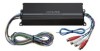
CONNECTIONS Fig. 3 and Fig. 4 - power wire
 |
View all Alpine KTP-445U manuals
Add to My Manuals
Save this manual to your list of manuals |
Page 6 highlights
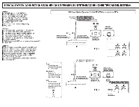
D· • Speakers/ Haut-parleurs/ Bocinas ,·(·G;e;n)t~;rt)t(v;rde RearlefV . 1 I (Green/Biack)/(verl/nolr)/(Verde/negro) : Gauchearn!re/ e I Posterior Izquierdo I I ~--~1 ~((WW~hh~lltlee~/)B/~(ibal~ackn~)c/();b/(lBa;ina,cn/cn;oo);lr)/=(B:ia:nc:o/n;e:gr;o 1:1e(!)~ Front lefV FGraounctahleIazvqaunieVrdo (Grey)/(grls)/(Grls) (Grey/Biack)/(gris/nolr)/(Grls/negro) : ~ ~r~:/ena~~~V 8'-J : Frontal derecha ~--~~(V~Io~le~l)/(~vlo~le~i)/~(V~Io:lel:a 1 , (VIoleVBiack) (vlolel/nolr)/(VIolela/negro) , (!)~ e Rear righV DPorostieteriaorrrid!reere/cha -ii- 'R"E'MiiiEriiR"N:o"NiAcr~v~iloN-o~ ~ r~~EcoririA;o-EiE;r:E;O",iio-REMiiro- (Biue/While)/(bleu/blanc)/(Azul/blanco) GNO/TERRE/Tierra (Biack)/(nolr)/(Negro) • BATTERY/BATTERIE!BATERiA (Yellow)/(jaune)/(Amarollo) KTP-445U Left end panei/Le panneau de gauche/panel de Ia izquierda Fig. 3 u w FRONT IN/ :~~~~EI ENTRADA FRONTAL REA~N/ ARRI RE ENTRE/ ENTRADA POSTERIOR CONNECTIONS (Fig. 3 and Fig. 4) Before making connections, be sure to turn the power off to all audio components. Connect the yellow battery lead from the amp directly to the positive(+) terminal of the vehicle's battery. Do not connect this lead to the fuse block. &cAUTION + Caution on connection terminals/parts • Keep electrically conductive objects away from the unit's terminals/parts (power terminals, fuses, speaker output terminals, RCA connectors, etc.). Doing so prevents a possible short circuit and damage to the unit. To prevent external noise from entering the audio system. Locate the unit and route the leads at least 10 em (315/16') away from the car harness. Keep the battery power leads as far away from other leads as possible. Connect the ground lead securely to a bare metal spot (remove any paint or grease if necessary) of the car chassis. Your Alpine dealer knows best about noise prevention measures so consult your dealer for further information. 0 Output/Power Connector • Input Connector • Fuse (15A X 1) USE ONLY THE CORRECT AMPERE RATING WHEN REPLACING FUSES. Failure to do so may result in fire or electric shock. 8 Output/Power Wire Harness • Speaker Output Wires Referring to "Cautions on speaker wire connections·; connect each speaker output wire to the correct corresponding speaker wire on the vehicle side. Note: Do not connect speaker leads together or to chassis ground. • Battery Lead (Yellow) There are two options: a. Connect battery lead to OEM radio fused circuit The OEM radio circuit has a fuse to protect your vehicle's electrical system in case of a short circuit. Do not connect the battery lead to the OEM radio circuit if the fuse rating is less than 15A. b. Connect battery lead directly to BATT+ Be sure to add a 15A fuse (sold separately) as close as possible to the battery's (+) terminal. 8 Remote Out Lead {Blue/White) Use this lead to turn on additional amplifiers. Note: This is a pass through Remote Turn-On signal from the head unit. 0 Ground Lead (Black) Connect this lead securely to a clean , bare metal spot on the vehicle's chassis. Verify this point to be a true ground by checking for continuity between that point and the negative(-) terminal of the vehicle's battery. Ground all your audio components to the same point on the chassis to prevent ground loops. • Input Wire Harness 4t Input Signal Wires There are two options: a. RCA Input Jacks (FRONT=Violet sleeve, REAR=Grey sleeve) Connect these jacks to the line out leads on your head unit using RCA extension cables (sold separately). b. Speaker Level Inputs Cut off the RCA jacks, then connect the correct corresponding speaker outputs from the head unit directly to these twisted pair wires. Note: For the "Speaker Level Input System" setting. connecting the Remote Turn-On Lead is not required due to the "REMOTE SENSING" function ofthis product. However, the "REMOTE SENSING " function may no/ work depending on the signal source connected. In such a case, connect the Remote Turn-On Lead to an incoming power supply wire (accessory power) in the ACC position. 8 Remote Turn-On Lead (Blue/White) Connect this lead to the remote turn-on or power antenna (positive trigger, (+) 12V only) lead of your head unit. Note: • See connection check list in Fig. 7. for more details. REMOTE TURN-ON/ACTIVATION DE LA TELECOMMANDE/ENCENDIDO REMOlD • (Biue/While)/(bleu!blanc)/(Azul!blanco) KTP-445U Right end panel/panneau de droite/panel de Ia derecha Fig.4
-
 1
1 -
 2
2 -
 3
3 -
 4
4 -
 5
5 -
 6
6 -
 7
7 -
 8
8 -
 9
9 -
 10
10 -
 11
11 -
 12
12 -
13
-
14
-
15
-
16
-
17
-
18
 |
 |
