Alpine KTP-445U Owners Manual - Page 7
Switch Settings Fig. 5 And Fig. 6, Connection Checklist Fig. 7 - install
 |
View all Alpine KTP-445U manuals
Add to My Manuals
Save this manual to your list of manuals |
Page 7 highlights
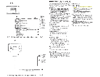
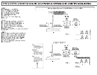
, ______ _ I I 48 • or:::::JD Note: Black squares indicate the positions ofthe switches. Remarque: Les carres noirs indiquent les positions des se/ecteurs. Nota : Los cuadros negros indican las posiciones de los interrupt ores. I I I I I I I ~ ~ I . ~ I ·~~P~'r or:::::JD KTP-445U Bottom panel/panneau inferieur/Panel inferior Note: When using speaker level inputs, both front and rear gain controls should be between minimum and 9 o'clock positionfor typical head unit volume Remarque: Si des entrees du niveau de hautparleur sont uti/isees, /es controles du gain avant et arriere doivent etre entre les positions minimales et 9 heures pour Ia gamme de volume typique de /'unite principale. Nota: AI usar entradas a nivel de bocina, ambos controles de ganancia deberim estar entre una posiciOn minima y Ia posicion de las 9 en punto para /ograr una gama de volumen tipica del amplificador principal. r-----, r-----, ~ : =: 1 FRONT 1 1 GAIN 1 h0- l ~~r lWJ l~l r~ KTP-445U Right end paneVpanneau de droite/panel de Ia derecha Fig.S Fig.6 KTP-445U ® @ I ~® -I (J) ® Fig. 7 SWITCH SETTINGS (Fig. 5 and Fig. 6) e. e High Pass Filter Frequency Selector Switches 12 OFF ~ 12 60Hz 12 60Hz 1 2 120Hz a) Slide switches 1 and 2 to the up position to turn off HP filter on front or rear channels [DEFAULT setting] b) Slide switch 1 to the down position and switch 2 to the up position to set the cutoff frequency to 60Hz on front or rear channels c) Slide switch 1 to the up position and switch 2 to the down position to set the cutoff frequency to 80Hz on front or rear channels. d) Slide switches 1 and 2 to the down position to set the cutoff frequency to 120Hz on front or rear channels e Input Configuration Switch 2CH a) Slide switch to the down position for 4 ~ channel input [DEFAULT setting] b) Slide switch to the up position for 2 5 4CH channel input Note: Input Configuration Switch should be in the up position for 2 CH bridged output system. • Input Signal Type Switch RCA ~ . SPKR a) Slide switch to the up position for RCA input signals [DEFAULT setting] b) Slide switch to the down position for speaker level input signals •· 8 Input Gain Adjustment Control Set the KTP-445U input gain to the minimum position. Using a dynamic CD as a source, increase the head unit volume until the output distorts. Then, reduce the volume 1 step (or until the output is no longer distorted). Now, increase the amplifier gain until the sound from the speakers become distorted. Reduce the gain slightly so the sound is no longer distorted to achieve the optimum gain setting. CONNECTION CHECKLIST (Fig. 7) Please check your head unit for the conditions listed below: (Fig. 7) a. The head unit does not have a remote turn-on or power antenna lead. b. The head unit's power antenna lead is activated only when the radio is on (turns off in the tape or CD Mode). c. The head unit's power antenna lead is logic level output (+) 5V, negative trigger (grounding type) , or cannot sustain (+) 12V when connected to other equipment in addition to the vehicle's power antenna. If any of the above conditions exist, the remote turn-on lead of your KTP-445U must be connected to a switched power source (ignition) in the vehicle. Be sure to use a 3A fuse as close as possible to this ignition tap. Using this connection method, the KTP445U will turn on and stay on as long as the ignition switch is on. If this is objectionable, a SPST (Single Pole, Single Throw) switch, in addition to the 3A fuse mentioned above, may be installed in-line on the KTP-445U turn-on lead. This switch will then be used to turn on (and off) the KTP-445U . Therefore, the switch should be mounted so that is accessible by the driver. Make sure the switch is turned off when the vehicle is not running. Otherwise, the amplifier will remain on and drain the battery. (j) Blue/White ~ Power Antenna @ Remote Turn-On Lead ® To other Alpine components' Remote Turn-On Leads @ SPST Switch (optional) @ r=usa(3A) . _ . __ (/) As close as possible to the vehicle's ignition tap @ Ignition Source
-
 1
1 -
 2
2 -
 3
3 -
 4
4 -
 5
5 -
 6
6 -
 7
7 -
 8
8 -
 9
9 -
 10
10 -
 11
11 -
 12
12 -
13
-
14
-
15
-
16
-
17
-
18
 |
 |
