Alpine T320 User Manual
Alpine T320 - V12 MRV Amplifier Manual
 |
View all Alpine T320 manuals
Add to My Manuals
Save this manual to your list of manuals |
Alpine T320 manual content summary:
- Alpine T320 | User Manual - Page 1
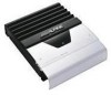
English Français Español R MRV-T420/MRV-T320 2/1 CHANNEL POWER AMPLIFIER • OWNER'S MANUAL Please read this manual to maximize your enjoyment of the outstanding performance and feature capabilities of the equipment, then retain the manual for future reference. • MODE D'EMPLOI Veuillez lire ce mode - Alpine T320 | User Manual - Page 2
nonrespect de ces instructions peut entraîner des blessures ou des dommages matériels. Español Introducción: A fin de familiarizarse con los controles y funciones de la unidad, lea detenidamente este MANUAL DE OPERACION. Nosotros en ALPINE esperamos que su nuevo MRV-T420/MRV-T320 le brinde muchos - Alpine T320 | User Manual - Page 3
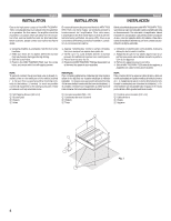
ón eléctrica y los cables conforme a lo descrito en el manual para evitar obstáculos durante la conducción. Los cables que obstaculizan PROBLEM APPEARS. Failure to do so may cause personal injury or damage to the product. Return it to your authorized Alpine dealer or the nearest Alpine Service - Alpine T320 | User Manual - Page 4
favor contacte a su distribuidor de Alpine autorizado. 1. Using the amplifier as a template, mark the four screw locations. 2. Make sure there are no objects behind the surface that may become damaged during drilling. 3. Drill the screw holes. 4. Position the MRV-T420/MRV-T320 over the screw holes - Alpine T320 | User Manual - Page 5
côté du ruban adhésif dou- ble-face fourni 7. 2) Appliquez un morceau de ruban adhésif double- face 7 sur la surface supérieure des deux supports 5. 3) Retirez le papier de l'autre côté du ruban adhésif double-face fourni 7. 7 5 NOTA: Aplicación de la cinta de doble cara Realice el procedimiento - Alpine T320 | User Manual - Page 6
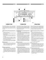
yellow battery lead from the amp directly to the positive (+) at least 10 cm away from the car harness. • Keep the battery power sortie du haut-parleur Le MRV-T420/MRV-T320 a deux ensembles de Alpine dispone de varios supresores de ruido Alpine. Solicítele más información. • Su proveedor Alpine - Alpine T320 | User Manual - Page 7
in case of a short circuit. If you need to extend this lead, the wire gauge should be 8 AWG or larger. 5 MRV-T420 ... 50A amp fuse (or two 25A fuses in parallel) MRV-T320 ... 30A amp fuse 5 Remote Turn-On Lead (Blue/White) (Sold Separately) Connect this lead to the remote turn-on or power antenna - Alpine T320 | User Manual - Page 8
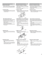
English 7 - 10 mm (9/32" - 3/8") Hexagon screw (M4)/Vis à six pans (M4)/ Tornillo hexagonal (M4) Français Lead end side of the product/Côté extrémité du produit/Extremo del producto Fig. 7 Lead/Conducteur/Alambre Lead Terminal/Borne de conducteur/Terminal Español Fig. 8 Cautions on wire lead - Alpine T320 | User Manual - Page 9
) the MRV-T420/MRV-T320. Therefore, the switch should be mounted so it is accessible to the driver. Make sure the switch is turned off when the vehicle is not running. Otherwise, the amplifier will remain on and drain the battery. 1 Blue/White 2 Power Antenna 3 Remote Turn-On Lead 4 To other Alpine - Alpine T320 | User Manual - Page 10
English MOUNTING THE TERMINAL COVER • The product's appearance can be improved by mount- ing the terminal cover on the main unit after installation. • Mount the terminal cover after the connections have been made and you have checked that operation is normal. Français MONTER LE COUVERCLE CACHE- - Alpine T320 | User Manual - Page 11
Adjustment Control Set the MRV-T420/MRV-T320 input gain to the minimum (4V) position. Using a dynamic CD as a source, increase the head unit volume until the output distorts. Then, reduce the volume 1 step (or until the output is no longer distorted). Now, increase the amplifier gain until the sound - Alpine T320 | User Manual - Page 12
puede ser confirmado con el indicador. • Protection indicator (PROTECTION) Blue Light Red Light Condition Amplifier circuit is normal. Amplifier circuit is abnormal. Solution Contact your authorized Alpine dealer. • Indicateur de protection (PROTECTION) Bleu Rouge Etat Allumé Le circuit de - Alpine T320 | User Manual - Page 13
46 É OFF LP Ü OFF HP Español (R) (L) ä 5 q Single Channel System/Système de canal unique/Sistema de canal único ã 46 -+ (MRV-T420) (L) INPUT (R) CH-1 CH-2 BRIDGED CH-2 CH-1 SPEAKER OUTPUT BATTERY REMOTE GND 25A 25A 25 25 FUSE POWER SUPPLY 5 â É OFF LP Ü OFF * HP - Alpine T320 | User Manual - Page 14
BRIDGED CH-2 CH-1 SPEAKER OUTPUT (R) â5 (L) BATTERY REMOTE GND 25A 25A 25 25 FUSE POWER SUPPLY ä5 Ü OFF LP â OFF HP (MRV-T420) MRV-T320 (L) INPUT (R) CH-1 CH-2 BRIDGED CH-2 CH-1 BATTERY REMOTE GND 25A 25A 25 25 SPEAKER OUTPUT ã - + FUSE POWER SUPPLY 5 q Speaker - Alpine T320 | User Manual - Page 15
20 Hz à 20 kHz) Par canal à 2 ohms (0,08% DHT) ........ MRV-T420: 110Wx2 MRV-T320: 80Wx2 Par canal à 2 ohms (0,3% DHT MRV-T420: 170Wx2 MRV-T320: 110Wx2 En pont à 4 ohms (0,3% DHT MRV-T420: 340Wx1 MRV-T320: 220Wx1 Puissance max. totale MRV-T420: 600W MRV-T320: 400W Réponse de fréquence 10 Hz à 50 - Alpine T320 | User Manual - Page 16
SERVICE CARE Français SOINS PRATIQUES Español CUIDADOS PRACTICOS IMPORTANT NOTICE This Amplifier manufacturer's instructions. MRV-T320 only 1 ACCESSOIRES • Couvercle d'achèvement 1 • Couvercle cache-bornes 1 • Support entrada del altavoz (MRV-T320 solamente 1 ALPINE ELECTRONICS, INC. Tokyo
-
 1
1 -
 2
2 -
 3
3 -
 4
4 -
 5
5 -
 6
6 -
 7
7 -
8
-
9
-
10
-
11
-
12
-
13
-
14
-
15
-
16
 |
 |

R
• OWNER'S MANUAL
Please read this manual to maximize your enjoyment of the outstanding
performance and feature capabilities of the equipment, then retain the
manual for future reference.
• MODE D'EMPLOI
Veuillez lire ce mode d'emploi pour tirer pleinement profit des
excellentes performances et fonctions de cet appareil, et conservez-le
pour toute référence future.
• MANUAL DE OPERACION
Lea este manual, por favor, para disfrutar al máximo de las
excepcionales prestaciones y posibilidades funcionales que ofrece el
equipo, luego guarde el manual para usarlo como referencia en el futuro.
MRV-T420/MRV-T320
2/1 CHANNEL POWER AMPLIFIER
CONTENTS
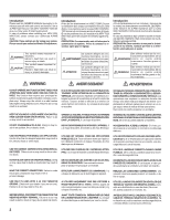
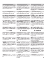
WARNING
..................................................................
2
CAUTION
...................................................................
3
INSTALLATION
..........................................................
4
CONNECTIONS
..........................................................
6
CONNECTIONS CHECK LIST
......................................
9
SWITCH SETTINGS
.................................................
11
SYSTEM DIAGRAMS
...............................................
13
SPECIFICATIONS
.....................................................
15
TABLE DES MATIERES
AVERTISSEMENT
......................................................
2
ATTENTION
................................................................
3
INSTALLATION
..........................................................
4
CONNEXIONS
............................................................
6
LISTE DE VERIFICATION DES CONNEXIONS
.............
9
REGLAGES DE COMMUTATEUR
..............................
11
DIAGRAMMES DU SYSTEME
..................................
13
SPECIFICATIONS
.....................................................
15
INDICE
ADVERTENCIA
...........................................................
2
PRUDENCIA
..............................................................
3
INSTALACION
............................................................
4
CONEXIONES
............................................................
6
LISTA DE VERIFICACION DE CONEXIONES
...............
9
AJUSTES DEL INTERRUPTOR
.................................
11
DIAGRAMAS DEL SISTEMA
....................................
13
ESPECIFICACIONES
................................................
15
Español
Français
English