Asus AP110 AP110 User Manual
Asus AP110 Manual
 |
View all Asus AP110 manuals
Add to My Manuals
Save this manual to your list of manuals |
Asus AP110 manual content summary:
- Asus AP110 | AP110 User Manual - Page 1
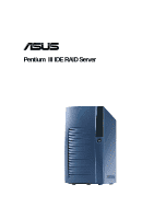
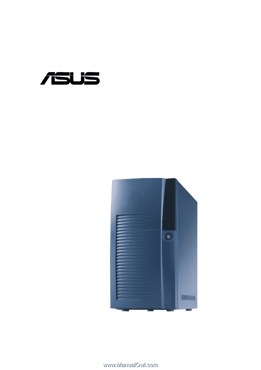
® AP110 Pentium® III IDE RAID Server User's Manual - Asus AP110 | AP110 User Manual - Page 2
permission of ASUSTeK COMPUTER INC. ("ASUS"). ASUS PROVIDES THIS MANUAL "AS IS" manual revision number. Manual updates are represented by the third digit in the manual revision number. For previous or updated manuals, BIOS, drivers, or product release information, contact ASUS at http://www.asus - Asus AP110 | AP110 User Manual - Page 3
/Copyrights 2 ASUS Contact Information 6 FCC/CDC Statements 7 Safety Precautions 8 Introduction: About This Manual 9 Audience 21 Remove the Screws 21 Remove the Cover 21 2.3 Motherboard Placement 22 Placement Direction 22 Motherboard Screws 22 2.4 Install a CPU 23 CPU Socket Location - Asus AP110 | AP110 User Manual - Page 4
Contents 2.5 Install System Memory 26 DIMM Sockets Location 26 Install a DIMM 26 2.6 Install a Hard Disk Drive 27 HDD Metal Cage 27 Remove the HDD Cage 27 Install the HDD 28 Replace the HDD Cage 28 Connect the Cables 29 IDE HDD Cabling 29 2.7 Replace the Covers 30 Re-install the Cover 30 - Asus AP110 | AP110 User Manual - Page 5
Contents Appendix A: Power Supply 43 A.1 General Description 44 A.2 Specifications 45 Input Characteristics 45 Output Characteristics 45 Over-Voltage Protection (OVP 45 Appendix B: Troubleshooting 47 B.1 Simple Fixes 48 5 - Asus AP110 | AP110 User Manual - Page 6
@asus.com WWW: www.asus.com FTP: ftp.asus.com.tw/pub/ASUS ASUS COMPUTER GmbH (Europe) Marketing Address: Fax: Email: Harkortstr. 25, 40880 Ratingen, BRD, Germany +49-2102-442066 [email protected] (for marketing requests only) Technical Support Hotline: MB/Others: +49-2102-9599-0 Notebook - Asus AP110 | AP110 User Manual - Page 7
. This equipment generates, uses and can radiate radio frequency energy and, if not installed and used in accordance with manufacturer's instructions, may cause harmful interference to radio communications. However, there is no guarantee that interference will not occur in a particular installation - Asus AP110 | AP110 User Manual - Page 8
• Any mechanical operation on this server must be conducted by certified or experienced engineers. • Before operating the server, carefully read all the manuals included with the server package. • Before using the server, make sure all cables are correctly connected and the power cables are not - Asus AP110 | AP110 User Manual - Page 9
About This Manual Introduction "About This Manual" introduces the contents of this document. This part includes the target audience, chapter description, and conventions used. It also lists other sources of information that are not contained in this manual. AP110 Server User's Manual 9 - Asus AP110 | AP110 User Manual - Page 10
This appendix lists the common problems that you may encounter while using the AP110 server. It lists the possible causes of the problems and offers solutions. You may refer to this part and try to solve simple problems before calling customer support. 10 Introduction: About This Manual - Asus AP110 | AP110 User Manual - Page 11
product and software updates. 1. ASUS CUV-2LSV Series Motherboard User's Manual This manual contains detailed information about the CUV-2LV motherboard. 2. ASUS Websites The ASUS websites worldwide provide updated information on ASUS hardware and softare products. The ASUS websites are listed in the - Asus AP110 | AP110 User Manual - Page 12
3) 250W ATX Power Supply 4) 50X CD-ROM Drive 5) 1.44MB Floppy Disk Drive 6) Support CD with Drivers and Utilities 7) User's Manuals (for system and motherboard) 8) ASUS System Management Agent (ASMA) Support CD If any of the above items is missing, contact your dealer. 12 Introduction: About - Asus AP110 | AP110 User Manual - Page 13
Chapter 1 This chapter describes the general features of the AP110 server. It includes sections on front panel, rear panel, and internal features of the server. System Overview AP110 Server User's Manual 13 - Asus AP110 | AP110 User Manual - Page 14
is a stylish tower chassis that accommodates the ASUS CUV-2LV motherboard. The server is powered by Intel® Pentium® III/Celeron™ processor, and supports the latest I/O, audio, and video technologies through the chipsets embedded on the motherboard. Following are highlights of the server's many - Asus AP110 | AP110 User Manual - Page 15
Panel Door Floppy Disk Drive Power LED IDE HDD LED Hot-Swap IDE Drives (optional) Power Button Reset Button CD-ROM Drive AP110 Server User's Manual 15 - Asus AP110 | AP110 User Manual - Page 16
1.3 Rear Panel Features The AP110 rear panel includes the external I/O ports. The following picture shows the cable connectors and the devices that you connect to the ports. PS/2 KB USB Serial VGA AC Power PS/2 Mouse Parallel RJ-45 Voltage Selector The switching power supply that came with the - Asus AP110 | AP110 User Manual - Page 17
standard components inside the AP110 server include the motherboard, power supply, floppy and CD-ROM drives, 6. IDE Cables for Hot-swap Drives (optional) 7. IDE RAID Card (optional) 8. CUV-2LV Motherboard NOTE The IDE RAID kit is optional and does not come with all models. If your server includes - Asus AP110 | AP110 User Manual - Page 18
18 Chapter 1: System Overview - Asus AP110 | AP110 User Manual - Page 19
Chapter 2 This chapter describes the hardware setup procedures that you have to perform when installing system components. Hardware Setup AP110 Server User's Manual 19 - Asus AP110 | AP110 User Manual - Page 20
2.1 Remove the Front Cover Follow these steps to remove the front panel. Unlock the Front Panel Insert the system key to the keylock and turn it 90 degrees counter clockwise to unlock the front panel cover. Remove the Screws Use a Phillips screwdriver to remove the two screws that secure the front - Asus AP110 | AP110 User Manual - Page 21
by circles. Remove the Cover Slide the cover for about an inch toward the front and lift it out of the chassis. AP110 Server User's Manual 21 - Asus AP110 | AP110 User Manual - Page 22
of the AP110 server are already installed as indicated in section "1.4 Internal Features". Refer to the motherboard user's manual for detailed technical information about the motherboard. When removing the motherboard, you need to remove the hot-swap trays and the CD-ROM drive first, because they - Asus AP110 | AP110 User Manual - Page 23
The Socket 370 on the CUV-2LV motherboard supports a Pentium III/Celeron CPU. This section tells you how to install a CPU. The following pictures show the CPU socket location on the motherboard, and the Pin 1 mark on , the fan heatsink is already attached to the CPU. AP110 Server User's Manual 23 - Asus AP110 | AP110 User Manual - Page 24
2.4 Install a CPU Unlock the CPU Socket Unlock the socket by pressing the lever sideways then lifting it up to a 90°-100° angle. Insert the CPU 1. Position the CPU above the socket such that its notched or marked corner matches the socket corner near the end of the lever. 2. Carefully insert the CPU - Asus AP110 | AP110 User Manual - Page 25
documentation that comes with the CPU for more information. Connect the Fan Cable Connect the CPU fan cable to the 3-pin CPU_FAN connector on the motherboard. Fan Cable CPU_FAN Connector AP110 Server User's Manual 25 - Asus AP110 | AP110 User Manual - Page 26
2.5 Install System Memor y DIMM Sockets Location The motherboard has three Dual Inline Memory Module (DIMM) sockets that support 3.3V SDRAM modules in 32, 64, 128, 256, 512MB, or 1GB densities. DIMM Sockets Install a DIMM 1. Unlock a DIMM socket by pressing the retaining clips outward. - Asus AP110 | AP110 User Manual - Page 27
. Cage Screw 2. Remove the screw on the side of the HDD cage. 3. Pull the HDD cage out of the chassis. Cage Screw AP110 Server User's Manual 27 - Asus AP110 | AP110 User Manual - Page 28
2.6 Install a Hard Disk Drive Install the HDD 1. Insert the HDD into the cage (label side up) until the holes on the sides align. 2. Secure the HDD with four screws (two on each side). Replace the HDD Cage 1. Carefully insert the HDD cage back into the chassis until it fits in place. 2. Secure the - Asus AP110 | AP110 User Manual - Page 29
at the back of the drive. IDE Cable 3. Connect the other end of the IDE cable to the primary IDE connector (blue connector) on the motherboard. Red Stripe to Pin 1 Power Cable (P3 or P4) Primary IDE Connector IDE HDD Cabling The picture on the left shows an installed HDD. AP110 - Asus AP110 | AP110 User Manual - Page 30
2.7 Replace the Covers NOTE If you are installing optional components such as the IDE RAID kit, proceed to Chapter 4 before replacing the covers. Re-install the Cover 1. Place the cover from the top of the chassis, leaving about an inch from the rear edge. 2. Slide the cover toward the rear panel - Asus AP110 | AP110 User Manual - Page 31
Chapter 3 This chapter tells how to get started with the AP110 server. Powering up the server basically includes connecting the cables and turning power on. Powering Up AP110 Server User's Manual 31 - Asus AP110 | AP110 User Manual - Page 32
3.1 Getting Star ted Make sure that you have completed the basic system installations in Chapter 2, then follow these steps to start up the server. Connect a Monitor Connect a monitor by plugging hte monitor cable to the video port (blue port) on the server rear panel. Video Port Connect the Power - Asus AP110 | AP110 User Manual - Page 33
Chapter 4 This chapter tells how to install the optional IDE RAID kit. Hardware Options AP110 Server User's Manual 33 - Asus AP110 | AP110 User Manual - Page 34
server supports a maximum of four hard disk drives, two external and two internal. The external HDD bays are available for an IDE RAID configuration using the optional IDE RAID Kit. This chapter tells about external HDD installation using the IDE RAID kit. Refer to Chapter 3 for instructions on - Asus AP110 | AP110 User Manual - Page 35
HDD. The drive tray interior includes an IDE cable and a power cable. Power Cable IDE Cable Hot-swap HDD Tray with Cover AP110 Server User's Manual 35 - Asus AP110 | AP110 User Manual - Page 36
4.2 Install a Hot-swap HDD Install HDD Tray Frame 1. Insert an HDD tray frame into one external drive bay as shown. 2. Secure the frame with four screws (two on each side). NOTE: Align the front screws with the holes labeled 1. 3. Follow steps 1 and 2 to install the second HDD tray frame. The - Asus AP110 | AP110 User Manual - Page 37
the cover to disengage it from the tray. 3. Slide the cover all the way back to remove it. Metal Latch Tray Lever AP110 Server User's Manual 37 - Asus AP110 | AP110 User Manual - Page 38
4.2 Install Hot-swap HDD Install an IDE Drive 1. Connect the IDE cable to the IDE connector at the back of the drive. 2. Connect the power cable to the power connector at the back of the drive. 3. Carefully place the drive into the tray until it fits in place. 4. Secure the drive with four screws ( - Asus AP110 | AP110 User Manual - Page 39
only the physical hardware connections of the RAID card, hot-swap HDDs, and IDE and power cables. For detailed instructions on RAID configuration, refer to the user's manual that came with the IDE RAID kit. Install a RAID Card 1. Remove the cover opposite the PCI1 expansion slot. 2. Carefully - Asus AP110 | AP110 User Manual - Page 40
tray: 1. Unlock the drive tray you desire to remove. 2. Lift up the tray handle. 3. Pull the tray out of the bay. 4. Refer to section 4.2 for instructions on installing a hotswap HDD. 40 Chapter 4: Hardware Options - Asus AP110 | AP110 User Manual - Page 41
motherboard. The CD-ROM drive overlaps with the top right corner of the motherboard purpose of removing the motherboard, you do not motherboard. In this instance, you also have to pull out the hot-swap drive trays because they, too, overlap with the motherboard. Top Right Corner of the Motherboard - Asus AP110 | AP110 User Manual - Page 42
4.5 CD-ROM Drive Re-install the CD-ROM Drive 1. Align the CD-ROM drive to its bay and carefully push it inward until it is flushed to the front panel. 2. Secure the drive with the screws that you removed earlier (two on each side). NOTE: Align the front screw with the hole labeled 1. 3. Connect the - Asus AP110 | AP110 User Manual - Page 43
Appendix A This appendix gives information on the 250-watt switching power supply that comes with the AP110 server. Power Supply AP110 Server User's Manual 43 - Asus AP110 | AP110 User Manual - Page 44
seven plugs labeled P1 to P7. The picture below shows the specific device assignments for the plugs. P2 P4 P3 P1 P5 P6 P7 P1. Motherboard ATX Power P2. CD-ROM Drive P3. Internal HDD P4. Internal HDD P5. Hot-swap HDD P6. Hot-swap HDD P7. Floppy Disk Drive 44 - Asus AP110 | AP110 User Manual - Page 45
, -12V, -5V, or +3.3V. By shorting +5Vsb, the power supply can latch down or automatically recover when the fault condition is removed. AP110 Server User's Manual 45 - Asus AP110 | AP110 User Manual - Page 46
46 Appendix A: Power Supply - Asus AP110 | AP110 User Manual - Page 47
appendix lists the common problems that you may encounter while using the AP110 server. It lists the possible causes of the problems and offers solutions. You may refer to this part and try to solve simple problems before calling customer support. Troubleshooting AP110 Server User's Manual 47 - Asus AP110 | AP110 User Manual - Page 48
on the system or the components. These problems only requires simple troubleshooting actions that you can perform by yourself. Problem Action The power LED on the server and the system supports. 2. Make sure that the DIMMs are properly installed on the sockets. 48 Appendix B: Troubleshooting - Asus AP110 | AP110 User Manual - Page 49
unstable Network connection not available Install the VIA utility drivers from the ASUS support CD. 1. Make sure the network cable is connector the RJ-45 port on the rear panel. 2. Make sure that you have installed the network drivers from the motherboard support CD. AP110 Server User's Manual 49 - Asus AP110 | AP110 User Manual - Page 50
50 Appendix B: Troubleshooting
-
 1
1 -
 2
2 -
 3
3 -
 4
4 -
 5
5 -
 6
6 -
 7
7 -
8
-
9
-
10
-
11
-
12
-
13
-
14
-
15
-
16
-
17
-
18
-
19
-
20
-
21
-
22
-
23
-
24
-
25
-
26
-
27
-
28
-
29
-
30
-
31
-
32
-
33
-
34
-
35
-
36
-
37
-
38
-
39
-
40
-
41
-
42
-
43
-
44
-
45
-
46
-
47
-
48
-
49
-
50
 |
 |
Pentium
®
III IDE RAID Server
®
AP110
User’s Manual