Asus G1-P5G43 User Manual - Page 16
Internal components
 |
View all Asus G1-P5G43 manuals
Add to My Manuals
Save this manual to your list of manuals |
Page 16 highlights
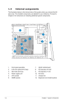
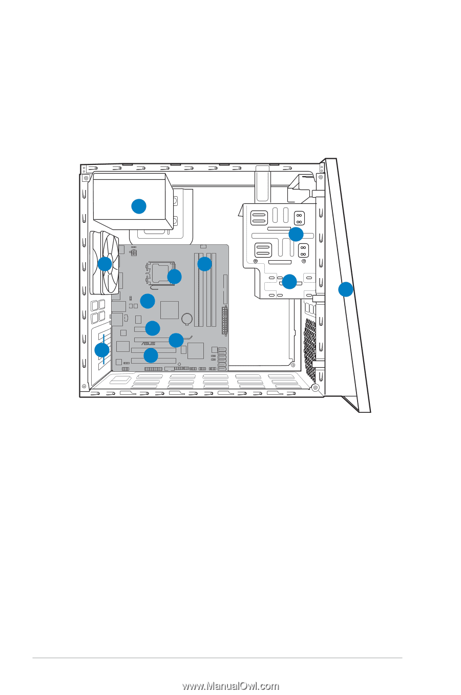
1.4 Internal components The illustration below is the internal view of the system when you remove the left side cover. The installed components are labeled for your reference. Proceed to Chapter 2 for instructions on installing additional system components. 4 11 6 5 7 9 8 12 10 2 3 1 1. Front panel assembly 2. 5.25-inch optical drive bays 3. Hard disk drive bay 4. Power supply unit 5. CPU socket 6. DIMM sockets 7. ASUS motherboard 8. PCI Express x16 slot 9. PCI Express x1 slot 10. PCI slots 11. Chassis fan 12. Expansion slot metal brackets 1-6 Chapter 1: System introduction
-
 1
1 -
2
-
3
-
4
-
5
-
6
-
7
-
8
-
9
-
10
-
 11
11 -
 12
12 -
 13
13 -
 14
14 -
 15
15 -
 16
16 -
 17
17 -
 18
18 -
 19
19 -
 20
20 -
 21
21 -
22
-
23
-
24
-
25
-
26
-
27
-
28
-
29
-
30
-
31
-
32
-
33
-
34
-
35
-
36
-
37
-
38
-
39
-
40
-
41
-
42
-
43
-
44
-
45
-
46
-
47
-
48
-
49
-
50
-
51
-
52
-
53
-
54
-
55
-
56
-
57
-
58
-
59
-
60
-
61
-
62
-
63
-
64
-
65
-
66
-
67
-
68
-
69
-
70
-
71
-
72
-
73
-
74
-
75
-
76
-
77
-
78
 |
 |
1-6
Chapter 1: System introduction
1.4
Internal components
The illustration below is the internal view of the system when you remove the left
side cover. The installed components are labeled for your reference. Proceed to
Chapter 2 for instructions on installing additional system components.
1.
Front panel assembly
2.
5.25-inch optical drive bays
3.
Hard disk drive bay
4.
Power supply unit
5.
CPU socket
6.
DIMM sockets
7.
ASUS motherboard
8.
PCI Express x16 slot
9.
PCI Express x1 slot
10.
PCI slots
11.
Chassis fan
12.
Expansion slot metal brackets
1
2
3
4
5
6
7
8
9
10
11
12