Asus G1-P5G43 User Manual - Page 19
Removing the side cover and front, panel assembly
 |
View all Asus G1-P5G43 manuals
Add to My Manuals
Save this manual to your list of manuals |
Page 19 highlights
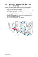
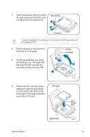
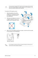
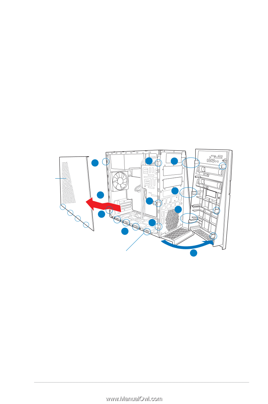
2.3 Removing the side cover and front panel assembly Follow the steps below to remove the side cover and front panel assembly. 1. Remove the cover screws on the rear panel. 2. Pull the side cover toward the rear panel until its hooks disengage from the chassis tab holes. Set the side cover aside. 3. Locate the front panel assembly hooks, then lift them until they disengage from the chassis. 4. Swing the front panel assembly to the right, until the hinge-like tabs on the right side of the assembly are exposed. 5. Remove the front panel assembly, then set it aside. Air duct 1 3 4 2 3 1 3 2 Chassis tab holes 4 4 4 ASUS G1-P5G43 2-3
-
 1
1 -
2
-
3
-
4
-
5
-
6
-
7
-
8
-
9
-
10
-
11
-
12
-
13
-
 14
14 -
 15
15 -
 16
16 -
 17
17 -
 18
18 -
 19
19 -
 20
20 -
 21
21 -
 22
22 -
 23
23 -
 24
24 -
25
-
26
-
27
-
28
-
29
-
30
-
31
-
32
-
33
-
34
-
35
-
36
-
37
-
38
-
39
-
40
-
41
-
42
-
43
-
44
-
45
-
46
-
47
-
48
-
49
-
50
-
51
-
52
-
53
-
54
-
55
-
56
-
57
-
58
-
59
-
60
-
61
-
62
-
63
-
64
-
65
-
66
-
67
-
68
-
69
-
70
-
71
-
72
-
73
-
74
-
75
-
76
-
77
-
78
 |
 |
2-3
ASUS G1-P5G43
2.3
Removing the side cover and front
panel assembly
Follow the steps below to remove the side cover and front panel assembly.
1.
Remove the cover screws on the rear panel.
2.
Pull the side cover toward the rear panel until its hooks disengage from the
chassis tab holes. Set the side cover aside.
3.
Locate the front panel assembly hooks, then lift them until they disengage
from the chassis.
4.
Swing the front panel assembly to the right, until the hinge-like tabs on the
right side of the assembly are exposed.
5.
Remove the front panel assembly, then set it aside.
Air duct
1
1
2
2
4
3
4
4
3
3
4
Chassis tab holes