Asus G1-P5G43 User Manual - Page 34
Installing storage drives
 |
View all Asus G1-P5G43 manuals
Add to My Manuals
Save this manual to your list of manuals |
Page 34 highlights
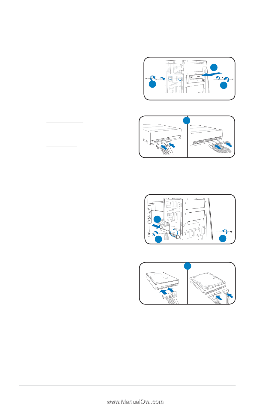
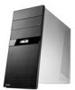
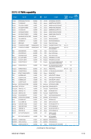
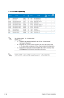
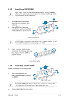
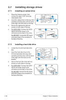
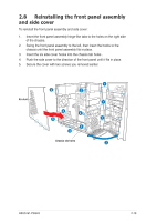
2.7 Installing storage drives 2.7.1 Installing an optical drive 1. Place the chassis upright, then remove the upper 5.25" drive bay metal plate cover. 2. Insert the optical drive to the bay, then carefully push the drive until its screw 3 holes align with the holes on the bay. 3. Secure the optical drive with two screws on both sides of the bay. 4. For SATA ODD: Connect the SATA signal and power plugs to the connectors at the back of the drive. SATA 4 For IDE ODD: Connect the IDE signal and power plugs to the connectors at the back of the drive. 2.7.2 Installing a hard disk drive 1. Locate the 3.5-inch hard disk drive bay. 2. Insert the hard disk drive to the 3.5-inch hard disk drive bay, then 2 carefully push the drive until its screw holes align with the holes on the bracket. 3 3. Secure the hard disk drive with two screws on both sides of the bay. 4. For SATA HDD: Connect the SATA signal and power plugs to the connectors at the back of the drive. SATA 4 For IDE HDD: Connect the IDE signal and power plugs to the connectors at the back of the drive. 2 3 IDE 3 IDE 2-18 Chapter 2: Basic installation
-
 1
1 -
2
-
3
-
4
-
5
-
6
-
7
-
8
-
9
-
10
-
11
-
12
-
13
-
14
-
15
-
16
-
17
-
18
-
19
-
20
-
21
-
22
-
23
-
24
-
25
-
26
-
27
-
28
-
 29
29 -
 30
30 -
 31
31 -
 32
32 -
 33
33 -
 34
34 -
 35
35 -
 36
36 -
 37
37 -
 38
38 -
 39
39 -
40
-
41
-
42
-
43
-
44
-
45
-
46
-
47
-
48
-
49
-
50
-
51
-
52
-
53
-
54
-
55
-
56
-
57
-
58
-
59
-
60
-
61
-
62
-
63
-
64
-
65
-
66
-
67
-
68
-
69
-
70
-
71
-
72
-
73
-
74
-
75
-
76
-
77
-
78
 |
 |