Asus MAXIMUS VI GENE MAXIMUS VI GENE User's Manual - Page 73
mPCIe Combo II installation, Installing the mPCIe Wi-Fi module
 |
View all Asus MAXIMUS VI GENE manuals
Add to My Manuals
Save this manual to your list of manuals |
Page 73 highlights
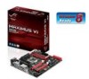
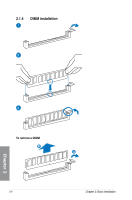
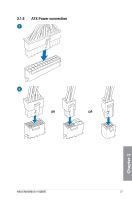
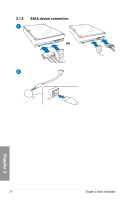
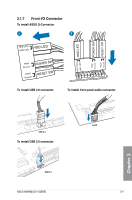
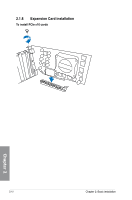
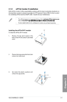
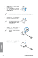
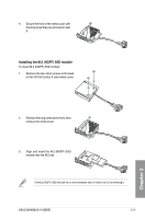
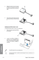
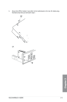
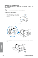
2.1.9 mPCIe Combo II installation ROG mPCIe Combo II offers expandability solutions with the latest connectivity standards via the proprietary connector onboard. It provides mini PCI Epxress 2.0 plus USB 2.0 which is useful for connecting mPCIe and M.2 (NGFF) SSD module into your motherboard. • The mPCIe Combo II card supports 26.8mm x 30mm h��a�lf�-�s�iz�e�d��m��P�C��I�e�m��o�d��u�le��o�n��o�n�e� side and �M�.�2��(N��G�F��F�)�t��y��p��e����2��2��4��2����S���S��D����c��a���r�d 2���2��m���m x���4���2�m��m�)��o�n�t�h�e��o�t�h�e�r�s�i�d�e�. • The M.2 (NGFF) SDD, Wi-Fi, and Bluetoorh modules are purchased separately. Installing the mPCIe Wi-Fi module To install the mPCIe Wi-Fi module: 1. Remove the two short screws at the back of the mPCIe Combo II card metal cover. 2. Remove the long screw at the front, then remove the metal cover. 3. Set aside the plastic washers and remove the cap screws. Chapter 2 ASUS MAXIMUS VI GENE 2-11
-
 1
1 -
2
-
3
-
4
-
5
-
6
-
7
-
8
-
9
-
10
-
11
-
12
-
13
-
14
-
15
-
16
-
17
-
18
-
19
-
20
-
21
-
22
-
23
-
24
-
25
-
26
-
27
-
28
-
29
-
30
-
31
-
32
-
33
-
34
-
35
-
36
-
37
-
38
-
39
-
40
-
41
-
42
-
43
-
44
-
45
-
46
-
47
-
48
-
49
-
50
-
51
-
52
-
53
-
54
-
55
-
56
-
57
-
58
-
59
-
60
-
61
-
62
-
63
-
64
-
65
-
66
-
67
-
 68
68 -
 69
69 -
 70
70 -
 71
71 -
 72
72 -
 73
73 -
 74
74 -
 75
75 -
 76
76 -
 77
77 -
 78
78 -
79
-
80
-
81
-
82
-
83
-
84
-
85
-
86
-
87
-
88
-
89
-
90
-
91
-
92
-
93
-
94
-
95
-
96
-
97
-
98
-
99
-
100
-
101
-
102
-
103
-
104
-
105
-
106
-
107
-
108
-
109
-
110
-
111
-
112
-
113
-
114
-
115
-
116
-
117
-
118
-
119
-
120
-
121
-
122
-
123
-
124
-
125
-
126
-
127
-
128
-
129
-
130
-
131
-
132
-
133
-
134
-
135
-
136
-
137
-
138
-
139
-
140
-
141
-
142
-
143
-
144
-
145
-
146
-
147
-
148
-
149
-
150
-
151
-
152
-
153
-
154
-
155
-
156
-
157
-
158
-
159
-
160
-
161
-
162
-
163
-
164
-
165
-
166
-
167
-
168
-
169
-
170
-
171
-
172
-
173
-
174
-
175
-
176
-
177
-
178
-
179
-
180
-
181
-
182
-
183
-
184
-
185
-
186
-
187
-
188
-
189
-
190
-
191
-
192
 |
 |