Asus MAXIMUS VI GENE MAXIMUS VI GENE User's Manual - Page 74
Basic Installation, the connectors on the Wi-Fi module.
 |
View all Asus MAXIMUS VI GENE manuals
Add to My Manuals
Save this manual to your list of manuals |
Page 74 highlights
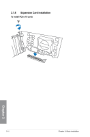
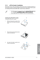
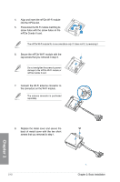
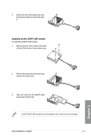
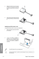
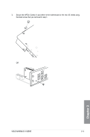
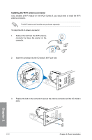
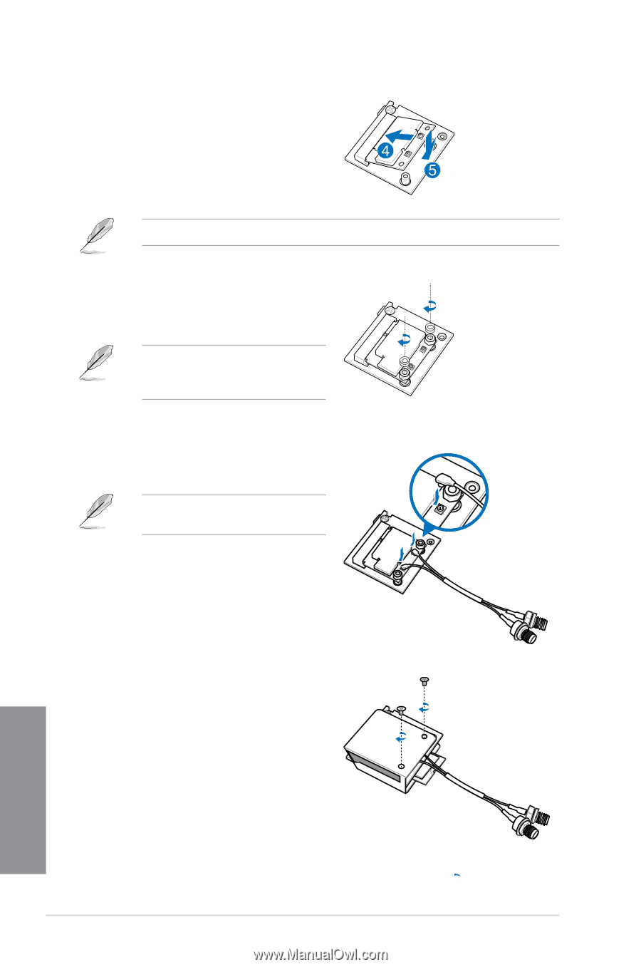
4. Align and insert the mPCIe Wi-Fi module into the mPCIe slot. 5. Press down the Wi-Fi module matching its screw holes with the screw holes on the mPCIe Combo II card. The mPCIe Wi-Fi module fits in one orientation only. If it does not fit, try reversing it. 6. Secure the mPCIe Wi-Fi module with the cap screws that you removed in step 3. Do not overtighten the screws to prevent damage to the mPCIe Wi-Fi module or mPCIe Combo II card. 7. Connect the Wi-Fi antenna connector to the connectors on the Wi-Fi module. The antenna connector is purchased separately. 8. Replace the metal cover and secure the back of metal cover with the two short screws that you removed in step 1. Chapter 2 2-12 Chapter 2: Basic Installation
-
 1
1 -
2
-
3
-
4
-
5
-
6
-
7
-
8
-
9
-
10
-
11
-
12
-
13
-
14
-
15
-
16
-
17
-
18
-
19
-
20
-
21
-
22
-
23
-
24
-
25
-
26
-
27
-
28
-
29
-
30
-
31
-
32
-
33
-
34
-
35
-
36
-
37
-
38
-
39
-
40
-
41
-
42
-
43
-
44
-
45
-
46
-
47
-
48
-
49
-
50
-
51
-
52
-
53
-
54
-
55
-
56
-
57
-
58
-
59
-
60
-
61
-
62
-
63
-
64
-
65
-
66
-
67
-
68
-
 69
69 -
 70
70 -
 71
71 -
 72
72 -
 73
73 -
 74
74 -
 75
75 -
 76
76 -
 77
77 -
 78
78 -
 79
79 -
80
-
81
-
82
-
83
-
84
-
85
-
86
-
87
-
88
-
89
-
90
-
91
-
92
-
93
-
94
-
95
-
96
-
97
-
98
-
99
-
100
-
101
-
102
-
103
-
104
-
105
-
106
-
107
-
108
-
109
-
110
-
111
-
112
-
113
-
114
-
115
-
116
-
117
-
118
-
119
-
120
-
121
-
122
-
123
-
124
-
125
-
126
-
127
-
128
-
129
-
130
-
131
-
132
-
133
-
134
-
135
-
136
-
137
-
138
-
139
-
140
-
141
-
142
-
143
-
144
-
145
-
146
-
147
-
148
-
149
-
150
-
151
-
152
-
153
-
154
-
155
-
156
-
157
-
158
-
159
-
160
-
161
-
162
-
163
-
164
-
165
-
166
-
167
-
168
-
169
-
170
-
171
-
172
-
173
-
174
-
175
-
176
-
177
-
178
-
179
-
180
-
181
-
182
-
183
-
184
-
185
-
186
-
187
-
188
-
189
-
190
-
191
-
192
 |
 |
2-12
Chapter 2: Basic Installation
Chapter 2
4.
Align and insert the mPCIe Wi-Fi module
into the mPCIe slot.
5.
Press down the Wi-Fi module matching its
screw holes with the screw holes on the
mPCIe Combo II card.
6.
Secure the mPCIe Wi-Fi module with the
cap screws that you removed in step 3.
7.
Connect the Wi-Fi antenna connector to
the connectors on the Wi-Fi module.
The mPCIe Wi-Fi module fits in one orientation only. If it does not fit, try reversing it.
Do not overtighten the screws to prevent
damage to the mPCIe Wi-Fi module or
mPCIe Combo II card.
The antenna connector is purchased
separately.
8.
Replace the metal cover and secure the
back of metal cover with the two short
screws that you removed in step 1.