Asus MAXIMUS VI GENE MAXIMUS VI GENE User's Manual - Page 76
Installing the mPCIe Combo II card, II card to the MPCIE_COMBO_II
 |
View all Asus MAXIMUS VI GENE manuals
Add to My Manuals
Save this manual to your list of manuals |
Page 76 highlights
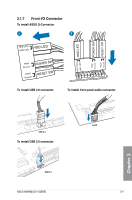
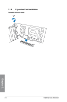
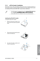
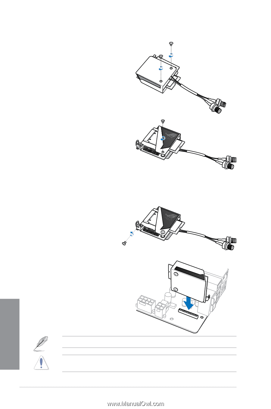
4. Replace the metal cover and secure the back of the metal cover with the two short screws that you removed in step 1. 5. Secure the front of the metal cover with the long screw that you removed in step 2. Installing the mPCIe Combo II card To install the mPCIe Combo II card to your motherboard: 1. Remove the black screw near the 36-2 pin connector. 2. L o c a t e t h e M P C I E _ C O M B O _ I I connector on the motherboard then align and insert the mPCIe Combo II card to the MPCIE_COMBO_II connector. The mPCIe Combo II fits in one orientation only. Insert the mPCIe Combo II carefully to prevent damage to the card, connector pins, or to the motherboard. 2-14 Chapter 2: Basic Installation Chapter 2
-
 1
1 -
2
-
3
-
4
-
5
-
6
-
7
-
8
-
9
-
10
-
11
-
12
-
13
-
14
-
15
-
16
-
17
-
18
-
19
-
20
-
21
-
22
-
23
-
24
-
25
-
26
-
27
-
28
-
29
-
30
-
31
-
32
-
33
-
34
-
35
-
36
-
37
-
38
-
39
-
40
-
41
-
42
-
43
-
44
-
45
-
46
-
47
-
48
-
49
-
50
-
51
-
52
-
53
-
54
-
55
-
56
-
57
-
58
-
59
-
60
-
61
-
62
-
63
-
64
-
65
-
66
-
67
-
68
-
69
-
70
-
 71
71 -
 72
72 -
 73
73 -
 74
74 -
 75
75 -
 76
76 -
 77
77 -
 78
78 -
 79
79 -
 80
80 -
 81
81 -
82
-
83
-
84
-
85
-
86
-
87
-
88
-
89
-
90
-
91
-
92
-
93
-
94
-
95
-
96
-
97
-
98
-
99
-
100
-
101
-
102
-
103
-
104
-
105
-
106
-
107
-
108
-
109
-
110
-
111
-
112
-
113
-
114
-
115
-
116
-
117
-
118
-
119
-
120
-
121
-
122
-
123
-
124
-
125
-
126
-
127
-
128
-
129
-
130
-
131
-
132
-
133
-
134
-
135
-
136
-
137
-
138
-
139
-
140
-
141
-
142
-
143
-
144
-
145
-
146
-
147
-
148
-
149
-
150
-
151
-
152
-
153
-
154
-
155
-
156
-
157
-
158
-
159
-
160
-
161
-
162
-
163
-
164
-
165
-
166
-
167
-
168
-
169
-
170
-
171
-
172
-
173
-
174
-
175
-
176
-
177
-
178
-
179
-
180
-
181
-
182
-
183
-
184
-
185
-
186
-
187
-
188
-
189
-
190
-
191
-
192
 |
 |
2-14
Chapter 2: Basic Installation
Chapter 2
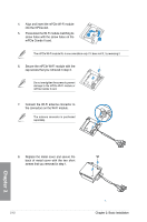
5.
Secure the front of the metal cover with
the long screw that you removed in step
2.
4.
Replace the metal cover and secure
the back of the metal cover with the
two short screws that you removed in
step 1.
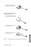
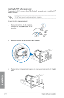
1.
Remove the black screw near the 36-2
pin connector.
Installing the mPCIe Combo II card
To install the mPCIe Combo II card to your motherboard:
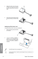
The mPCIe Combo II fits in one orientation only.
2.
Locate the MPCIE_COMBO_II
connector on the motherboard then
align and insert the mPCIe Combo
II card to the MPCIE_COMBO_II
connector.
Insert the mPCIe Combo II carefully to prevent damage to the card, connector pins, or to
the motherboard.