Asus P4RD1-MX Motherboard DIY Troubleshooting Guide
Asus P4RD1-MX Manual
 |
View all Asus P4RD1-MX manuals
Add to My Manuals
Save this manual to your list of manuals |
Asus P4RD1-MX manual content summary:
- Asus P4RD1-MX | Motherboard DIY Troubleshooting Guide - Page 1
P4RD1-MX Motherboard - Asus P4RD1-MX | Motherboard DIY Troubleshooting Guide - Page 2
express written permission of ASUSTeK COMPUTER INC. ("ASUS"). Product warranty or service will not be extended if: (1) the ASUS HAS BEEN ADVISED OF THE POSSIBILITY OF SUCH DAMAGES ARISING FROM ANY DEFECT OR ERROR IN THIS MANUAL OR PRODUCT. SPECIFICATIONS AND INFORMATION CONTAINED IN THIS MANUAL - Asus P4RD1-MX | Motherboard DIY Troubleshooting Guide - Page 3
vii About this guide viii Typography ix P4RD1-MX specifications summary x Chapter 1: Product introduction 1.1 Welcome 1-2 1.2 Package contents 1-2 1.3 Special features 1-3 1.3.1 Product highlights 1-3 1.3.2 Innovative ASUS features 1-5 1.4 Before you proceed 1-6 1.5 Motherboard overview - Asus P4RD1-MX | Motherboard DIY Troubleshooting Guide - Page 4
BIOS 2 utility 2-6 2.1.4 ASUS EZ Flash utility 2-8 2.1.5 ASUS Update utility 2-9 2.2 BIOS setup program 2-12 2.2.1 BIOS menu screen 2-13 2.2.2 Menu bar 2-13 2.2.3 Navigation keys 2-13 2.2.4 Menu items 2-14 2.2.5 Sub-menu items 2-14 2.2.6 Configuration fields 2-14 2.2.7 Pop-up window - Asus P4RD1-MX | Motherboard DIY Troubleshooting Guide - Page 5
2-33 2.7 Exit menu 2-35 Chapter 3: Software support 3.1 Installing an operating system 3-2 3.2 Support CD information 3-2 3.2.1 Running the support CD 3-2 3.2.2 Drivers menu 3-3 3.2.3 Utilities menu 3-4 3.2.4 Make Disk menu 3-5 3.2.5 Manuals menu 3-6 3.2.5 ASUS Contact information 3-6 v - Asus P4RD1-MX | Motherboard DIY Troubleshooting Guide - Page 6
. This equipment generates, uses and can radiate radio frequency energy and, if not installed and used in accordance with manufacturerʼs instructions, may cause harmful interference to radio communications. However, there is no guarantee that interference will not occur in a particular installation - Asus P4RD1-MX | Motherboard DIY Troubleshooting Guide - Page 7
Contact a qualified service technician or your retailer. Operation safety • Before installing the motherboard and adding devices on it, carefully read all the manuals that came with the • If you encounter technical problems with the product, contact a qualified service technician or your retailer. vii - Asus P4RD1-MX | Motherboard DIY Troubleshooting Guide - Page 8
the BIOS parameters are also provided. • Chapter 3: Software support This chapter describes the contents of the support CD that comes with the motherboard package. Where to find more information Refer to the following sources for additional information and for product and software updates. 1. ASUS - Asus P4RD1-MX | Motherboard DIY Troubleshooting Guide - Page 9
of the following symbols used throughout this manual. DANGER/WARNING: Information to prevent injury to yourself when trying to complete a task. CAUTION: Information to prevent damage to the components when trying to complete a task. IMPORTANT: Instructions that you MUST follow to complete a task - Asus P4RD1-MX | Motherboard DIY Troubleshooting Guide - Page 10
P4RD1-MX specifications summary CPU Chipset Socket 478 for Intel® Pentium® 4/Celeron® processor Supports Intel® Hyper-Threading Technology Northbridge: ATi® RADEON XPRESS 200 Southbridge: ULI® M1573 Front Side Bus 800/533 MHz Memory 2 x 184-pin DIMM sockets support unbufferred non-ECC 400/333 - Asus P4RD1-MX | Motherboard DIY Troubleshooting Guide - Page 11
P4RD1-MX specifications summary Rear panel Internal connectors Power requirement Form Factor Support CD contents 1 x Parallel port 1 x VGA port 1 x LAN (RJ-45) port 4 x USB 2.0 ports 1 x Serial (COM) port 1 x PS/2 keyboard port 1 x PS/2 mouse port 6-channel audio ports 1 x Floppy disk drive - Asus P4RD1-MX | Motherboard DIY Troubleshooting Guide - Page 12
xii - Asus P4RD1-MX | Motherboard DIY Troubleshooting Guide - Page 13
This chapter describes the motherboard features and the new technologies introPdruoc1dtuiocnt it supports. ASUS P4RD1-MX 1-1 - Asus P4RD1-MX | Motherboard DIY Troubleshooting Guide - Page 14
for the following items. Motherboard ASUS P4RD1-MX motherboard Cables 1 x Serial ATA signal cable 1 x Serial ATA power cable 1 x Ultra DMA 133/100/66 cable 1 x Floppy disk drive cable Accessories I/O shield Application CD ASUS motherboard support CD Documentation User guide If any of the - Asus P4RD1-MX | Motherboard DIY Troubleshooting Guide - Page 15
1-16 for details. Serial ATA technology The motherboard supports the Serial ATA technology through the Serial ATA interfaces. The SATA specification allows for thinner, more flexible cables with lower pin count, reduced voltage requirement, and up to 150 MB/s data transfer rate. ASUS P4RD1-MX 1-3 - Asus P4RD1-MX | Motherboard DIY Troubleshooting Guide - Page 16
comes with the ADI AD1986A high-definition audio CODEC that lets you enjoy high-quality 6-channel audio without having to buy advanced sound cards. S/PDIF digital sound ready The motherboard supports the S/PDIF Out function through the S/PDIF interfaces on the rear panel and at midboard. The - Asus P4RD1-MX | Motherboard DIY Troubleshooting Guide - Page 17
the system hangs due to overclocking. When the system hangs due to overclocking, C.P.R. eliminates the need to open the system chassis and clear the RTC data. Simply shut down and reboot the system, and the BIOS automatically restores the CPU previous setting for each parameter. ASUS P4RD1-MX 1-5 - Asus P4RD1-MX | Motherboard DIY Troubleshooting Guide - Page 18
that you should shut down the system and unplug the power cable before removing or plugging in any motherboard component. The illustration below shows the location of the onboard LED. P4RD1-MX ® P4RD1-MX Onboard LED SB_PWR ON Standby Power OFF Powered Off 1-6 Chapter 1: Product introduction - Asus P4RD1-MX | Motherboard DIY Troubleshooting Guide - Page 19
as indicated in the image below. 1.5.2 Screw holes Place six (6) screws into the holes indicated by circles to secure the motherboard to the chassis. Do not overtighten the screws! Doing so can damage the motherboard. Place this side towards the rear of the chassis P4RD1-MX ® ASUS P4RD1-MX 1-7 - Asus P4RD1-MX | Motherboard DIY Troubleshooting Guide - Page 20
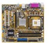
) DDR DIMM_B1 (64 bit,184-pin module) EATXPWR PARALLEL PORT VGA USB12 USBPW12 USBPW34 LAN_USB34 Top:Line In Center:Line Out Below:Mic In ATX12V TV_C ATI RADEON XPRESS 200 PWR_FAN RTL8201CL PCIEX1_1 PCIEX16 P4RD1-MX ® CR2032 3V Lithium Cell CMOS Power PCI1 SPDIF_OUT AD1986A AAFP CD - Asus P4RD1-MX | Motherboard DIY Troubleshooting Guide - Page 21
the instructions in this section do not match the CPU documentation, follow the latter. Installing the CPU To install a CPU: 1. Locate the CPU socket on the motherboard. Gold Arrow P4RD1-MX ® P4RD1-MX CPU Socket the CPU does not fit in completely. Socket Lever 90 - 100 ASUS P4RD1-MX 1-9 - Asus P4RD1-MX | Motherboard DIY Troubleshooting Guide - Page 22
Hyper-Threading Technology item in the BIOS to ensure system stability and performance. • Installing Windows® XP Service Pack 1 or later version is recommended. • Make sure to enable the Hyper-Threading Technology item in BIOS before installing a supported operating system. • For more information on - Asus P4RD1-MX | Motherboard DIY Troubleshooting Guide - Page 23
two 184-pin Double Data Rate (DDR) Dual Inline Memory Modules (DIMM) sockets. The motherboard supports dual channel memory architechture. The following figure illustrates the location of the sockets: P4RD1-MX ® P4RD1-MX 184-pin DDR DIMM sockets DIMM_A1 DIMM_B1 104 Pins 80 Pins ASUS P4RD1-MX 1-11 - Asus P4RD1-MX | Motherboard DIY Troubleshooting Guide - Page 24
obtain memory modules from the same vendor. • Due to chipset limitation, DIMM modules with double-sided x16 memory chips are not supported in this motherboard. • Visit the ASUS website for the latest DDR 400 MHz (FSB 800/533) Qualified Vendors Lists. Table 1 Recommended memory configurations For dual - Asus P4RD1-MX | Motherboard DIY Troubleshooting Guide - Page 25
to do so may cause severe damage to both the motherboard and the components. 1. Unlock a DIMM socket by Support the DIMM lightly with your fingers when pressing the retaining clips. The DIMM might get damaged when it flips out with extra force. 2. Remove the DIMM from the socket. ASUS P4RD1-MX - Asus P4RD1-MX | Motherboard DIY Troubleshooting Guide - Page 26
the expansion cards that they support. Make sure to unplug the injury and damage motherboard components. 1.8.1 Installing Remove the system unit cover (if your motherboard is already installed in a chassis). the necessary BIOS settings, if any. See Chapter 2 for information on BIOS setup. 2. - Asus P4RD1-MX | Motherboard DIY Troubleshooting Guide - Page 27
- - used - - shared - - - - - - When using PCI cards on shared slots, ensure that the drivers support "Share IRQ" or that the cards do not need IRQ assignments. Otherwise, conflicts will arise between the two PCI groups, making the system unstable and the card inoperable. ASUS P4RD1-MX 1-15 - Asus P4RD1-MX | Motherboard DIY Troubleshooting Guide - Page 28
, SCSI card, USB card, and other cards that comply with PCI specifications. The figure shows a LAN card installed on a PCI slot. 1.8.5 PCI Express x16 slot This motherboard supports PCI Express x16 graphic cards that comply with the PCI Express specifications. The figure shows a graphics card installed - Asus P4RD1-MX | Motherboard DIY Troubleshooting Guide - Page 29
CMOS You do not need to clear the RTC when the system hangs due to overclocking. For system failure due to overclocking, use the C.P.R. (CPU Parameter Recall) feature. Shut down and reboot the system so the BIOS can automatically reset parameter settings to default values. ASUS P4RD1-MX 1-17 - Asus P4RD1-MX | Motherboard DIY Troubleshooting Guide - Page 30
and USBPWR78 jumper is for the internal USB connectors that you can connect to additional USB ports. P4RD1-MX ® USBPW12 USBPW34 2 1 +5V (Default) 3 2 +5VSB USBPW56 USBPW78 12 23 P4RD1-MX USB device wake-up +5V (Default) +5VSB • The USB device wake-up feature requires a power supply that - Asus P4RD1-MX | Motherboard DIY Troubleshooting Guide - Page 31
the Space Bar). This feature requires an ATX power supply that can supply at least 1A on the +5VSB lead, and a corresponding setting in the BIOS. P4RD1-MX ® KBPWR 12 23 +5V (Default) +5VSB P4RD1-MX Keyboard power setting ASUS P4RD1-MX 1-19 - Asus P4RD1-MX | Motherboard DIY Troubleshooting Guide - Page 32
100M Linking/ Green Status Description OFF No Link Blicking 100M Activity 10Mbps 100Mbps LED LED LAN port 4. Line In jack. This Line In (light blue) jack connects a tape player or other audio sources. In 6-channel configuration, the function of this port becomes Surround Out. 5. Line Out - Asus P4RD1-MX | Motherboard DIY Troubleshooting Guide - Page 33
Audio 2, 4, or 6-channel Universal Serial Bus (USB) ports are available for connecting USB 2.0 devices. 9. VGA port. This port connects to VGA or LCD monitor. 10. Serial connector. This 9-pin COM1 port is for cable to PIN 1. P4RD1-MX ® PIN 1 P4RD1-MX Floppy disk drive connector ASUS P4RD1-MX 1-21 - Asus P4RD1-MX | Motherboard DIY Troubleshooting Guide - Page 34
has three connectors: a blue connector for the primary IDE connector on the motherboard, a black connector for an Ultra DMA 133/100/66 IDE slave device cable for Ultra DMA 133/100/66 IDE devices. PRI_IDE SEC_IDE P4RD1-MX ® P4RD1-MX IDE connector 11 NOTE: Orient the red markings (usually zigzag) - Asus P4RD1-MX | Motherboard DIY Troubleshooting Guide - Page 35
P4RD1-MX ® P4RD1-MX SATA connectors SATA2 SATA1 GND RSATA_TXP1 RSATA_TXN1 GND RSATA_RXP1 RSATA_RXN1 GND Important notes on Serial ATA • Due to chipset limitation, you cannot configure a RAID 0 set or JBOD with more than two hard drives. • Install the Windows® 2000 Service Pack 4 or the Windows® XP - Asus P4RD1-MX | Motherboard DIY Troubleshooting Guide - Page 36
air flow inside the system may damage the motherboard components. These are not jumpers! DO NOT place jumper caps on the fan connectors. P4RD1-MX ® CPU_FAN PWR_FAN CHA_FAN CPU_FAN Rotation +12V GND PWR_FAN Rotation +12V GND CHA_FAN P4RD1-MX Fan connectors Rotation +12V GND 6. USB connectors (10 - Asus P4RD1-MX | Motherboard DIY Troubleshooting Guide - Page 37
+12 Volts +3 Volts 8. Optical drive audio connector (4-pin CD) This connector is for the 4-pin audio cable that connects to the audio connector at the back of the optical drive. CD Left Audio Channel Ground Ground Right Audio Channel P4RD1-MX ® P4RD1-MX CD audio connector ASUS P4RD1-MX 1-25 - Asus P4RD1-MX | Motherboard DIY Troubleshooting Guide - Page 38
caps only when you intend to use the chassis intrusion detection feature. CHASSIS P4RD1-MX ® (Default) P4RD1-MX Chassis intrusion connector 10. Digital Audio connector (4-1 pin SPDIF_OUT) This connector is for the S/PDIF audio module to allow digital sound output. Connect one end of the S/PDIF - Asus P4RD1-MX | Motherboard DIY Troubleshooting Guide - Page 39
audio module to this connector to avail the high-definition audio features of the motherboard. • By default, this connector is set to legacy ACʼ97 audio. If you want to connect a high-definition front panel audio module to this connector, enable the HD Audio Controller item in the BIOS. ASUS P4RD1-MX - Asus P4RD1-MX | Motherboard DIY Troubleshooting Guide - Page 40
13. System panel connector (20-pin PANEL) This connector supports several chassis-mounted functions. PLED SPEAKER PLED+ PLED+5V Ground Ground Speaker PANEL IDE_LED+ IDE_LED- PWR Ground Reset Ground P4RD1-MX ® IDE LED P4RD1-MX System panel connector RESET PWR The sytem panel connector is - Asus P4RD1-MX | Motherboard DIY Troubleshooting Guide - Page 41
This chapter tells how to change the system settings through the BIOS Setup menus. Detailed descriptions of the BIOS parameters are also provided. 2 BIOS setup ASUS P4RD1-MX 2-1 - Asus P4RD1-MX | Motherboard DIY Troubleshooting Guide - Page 42
.) 2. ASUS CrashFree BIOS 2 (Updates the BIOS using a bootable floppy disk or the motherboard support CD when the BIOS file fails or gets corrupted.) 3. ASUS EZ Flash (Updates the BIOS in DOS using a floppy disk or the motherboard support CD.) 4. ASUS Update (Updates the BIOS in Windows® environment - Asus P4RD1-MX | Motherboard DIY Troubleshooting Guide - Page 43
then follow screen instructions to continue. 2. Copy the original or the latest motherboard BIOS file to the bootable floppy disk. 2.1.2 AFUDOS utility The AFUDOS utility allows you to update the BIOS file in DOS name. A:\>afudos /oOLDBIOS1.ROM Main filename Extension name ASUS P4RD1-MX 2-3 - Asus P4RD1-MX | Motherboard DIY Troubleshooting Guide - Page 44
DOS prompt after copying the current BIOS file. Updating the BIOS file To update the BIOS file using the AFUDOS utility: 1. Visit the ASUS website (www.asus.com) and download the latest BIOS file for the motherboard. Save the BIOS file to a bootable floppy disk. Write the BIOS filename on a piece of paper - Asus P4RD1-MX | Motherboard DIY Troubleshooting Guide - Page 45
(C) 2003 American Megatrends, Inc. All rights reserved. WARNING!! Do not turn off power during flash BIOS Reading file ..... done Reading flash .... done Advance Check......... Erasing flash ..... done Writing flash ..... done Verifying flash ... done Please restart your computer A:\> ASUS P4RD1-MX 2-5 - Asus P4RD1-MX | Motherboard DIY Troubleshooting Guide - Page 46
ASUS CrashFree BIOS 2 utility The ASUS CrashFree BIOS 2 is an auto recovery tool that allows you to restore the BIOS file when it fails or gets corrupted during the updating process. You can update a corrupted BIOS file using the motherboard support CD or the floppy disk that contains the updated BIOS - Asus P4RD1-MX | Motherboard DIY Troubleshooting Guide - Page 47
while updating the BIOS! Doing so can cause system boot failure! 4. Restart the system after the utility completes the updating process. The recovered BIOS may not be the latest BIOS version for this motherboard. Visit the ASUS website (www.asus.com) to download the latest BIOS file. ASUS P4RD1-MX - Asus P4RD1-MX | Motherboard DIY Troubleshooting Guide - Page 48
1. Visit the ASUS website (www.asus.com) to download the latest BIOS file for the motherboard and rename the same to P4RD1MX.ROM. 2. Save the BIOS file to a floppy disk, then restart the system. 3. Press + during POST to display the following. EZFlash starting BIOS update Checking for floppy - Asus P4RD1-MX | Motherboard DIY Troubleshooting Guide - Page 49
drive. The Drivers menu appears. 2. Click the Utilities tab, then click Install ASUS Update VX.XX.XX. See page 3-4 for the Utilities screen menu. 3. The ASUS Update utility is copied to your system. Quit all Windows® applications before you update the BIOS using this utility. ASUS P4RD1-MX 2-9 - Asus P4RD1-MX | Motherboard DIY Troubleshooting Guide - Page 50
through the Internet To update the BIOS through the Internet: 1. Launch the ASUS Update utility from the Windows® desktop by clicking Start > Programs > ASUS > ASUSUpdate > ASUSUpdate. The ASUS Update main window appears. 2. Select Update BIOS from the Internet option from the drop-down menu, then - Asus P4RD1-MX | Motherboard DIY Troubleshooting Guide - Page 51
> ASUS > ASUSUpdate > ASUSUpdate. The ASUS Update main window appears. 2. Select Update BIOS from a file option from the drop-down menu, then click Next. 3. Locate the BIOS file from the Open window, then click Open. 4. Follow the screen instructions to complete the update process. ASUS P4RD1-MX - Asus P4RD1-MX | Motherboard DIY Troubleshooting Guide - Page 52
setup program This motherboard supports a programmable firmware chip that you can update using the provided utility described in section "2.1 Managing and updating your BIOS." Use the BIOS Setup program when you are installing a motherboard, reconfiguring your system, or prompted to "Run Setup". This - Asus P4RD1-MX | Motherboard DIY Troubleshooting Guide - Page 53
2.2.1 BIOS menu screen Menu items Menu bar Configuration fields General help System Time System Date Legacy Diskette A Primary IDE Master Primary IDE keys to select items in the menu and change the settings. Some of the navigation keys differ from one screen to another. ASUS P4RD1-MX 2-13 - Asus P4RD1-MX | Motherboard DIY Troubleshooting Guide - Page 54
Configuration System Information [11:10:19] [Thu 03/27/2003] [1.44M, 3.5 in] [English] :[ST320413A] :[ASUS CD-S340] :[Not Detected] :[Not Detected] :[Not Detected] :[Not Detected] Use [ENTER], [TAB] or General Help F10 Save and Exit ESC Exit Pop-up window Scroll bar 2-14 Chapter 2: BIOS setup - Asus P4RD1-MX | Motherboard DIY Troubleshooting Guide - Page 55
appears, giving you an overview of the basic system information. Refer to section "2.2.1 BIOS menu screen" for information on the menu screen items and how to navigate through them Disabled] [360K, 5.25 in.] [1.2M , 5.25 in.] [720K , 3.5 in.] [1.44M, 3.5 in.] [2.88M, 3.5 in.] ASUS P4RD1-MX 2-15 - Asus P4RD1-MX | Motherboard DIY Troubleshooting Guide - Page 56
DMA-2 Ultra DMA : Ultra DMA-5 SMART Monitoring: Supported Type [Auto] LBA/Large Mode [Auto] Block(Multi-sector Transfer) M [Auto] PIO Mode [Auto] DMA Mode [Auto] SMART Monitoring [Auto] 32Bit Data Transfer [Disabled] The BIOS automatically detects the values opposite the dimmed - Asus P4RD1-MX | Motherboard DIY Troubleshooting Guide - Page 57
: 08/29/05 Processor Type Speed Count : Genuine Intel(R) CPU 2.80GHz : 2800 MHz : 1 System Memory Size : 512MB AMI BIOS Displays the auto-detected BIOS information Processor Displays the auto-detected CPU specification System Memory Displays the auto-detected system memory ASUS P4RD1-MX 2-17 - Asus P4RD1-MX | Motherboard DIY Troubleshooting Guide - Page 58
> to display the configuration options. USB Configuration Module Version - 2.24.0-10.4 USB Devices Enabled: None USB Controller Legacy USB Support USB 2.0 Controller Mode BIOS EHCI Hand-Off [USB OHCI + EHCI] [Auto] [HiSpeed] [Enabled] The Module Version and USB Devices Enabled items show the auto - Asus P4RD1-MX | Motherboard DIY Troubleshooting Guide - Page 59
the legacy USB support is disabled. Con overclocking configuration options: Manual - allows you to individually set overclocking parameters. Auto - loads the optimal settings for the system. Standard - loads the standard settings for the system. Overclock Profile - loads overclocking ASUS P4RD1-MX 2-19 - Asus P4RD1-MX | Motherboard DIY Troubleshooting Guide - Page 60
setting the memory voltage. Setting a very high memory voltage may damage the memory module(s)! The following item appears only when the AI Overclocking item is set to [Manual]. CPU Frequency [XXX] (value is auto-detected) Indicates the frequency sent by the clock generator to the system bus and PCI - Asus P4RD1-MX | Motherboard DIY Troubleshooting Guide - Page 61
Function Microcode Updation Max CPUID detected by BIOS. Use the support CPUs with extended CPUID functions. Configuration options: [Disabled] [Enabled] CPU Internal Thermal Control [Auto] Disables or sets the CPU internal thermal control. Configuration options: [Auto] [Disabled] ASUS P4RD1-MX - Asus P4RD1-MX | Motherboard DIY Troubleshooting Guide - Page 62
card. Configuration options: [Disabled] [Enabled] UMA Frame Buffer Size [64MB] Sets the UMA frame buffer size. Configuration options: [32MB] [64MB] [128MB] 2-22 Chapter 2: BIOS setup - Asus P4RD1-MX | Motherboard DIY Troubleshooting Guide - Page 63
parameters are set according to the DRAM SPD (Serial Presence Detect). When disabled, you can manually set the DRAM timing parameters through the DRAM sub-tems. The following sub-items appear when this figuration options: [15.625 us] [3.9 us] [7.8 us] [31.3 us] [62.5 us] [125 us] ASUS P4RD1-MX 2-23 - Asus P4RD1-MX | Motherboard DIY Troubleshooting Guide - Page 64
options: [SATA Mode] [Raid Mode] Ethernet Controller [Enabled] Enables or disables the Onboard LAN controller. Configuration options: [Disabled] [Enabled] OnBoard LAN Boot ROM [Disabled] Enables or disables the LAN Boot ROM. Configuration options: [Disabled] [Enabled] 2-24 Chapter 2: BIOS setup - Asus P4RD1-MX | Motherboard DIY Troubleshooting Guide - Page 65
[3F8/IRQ4] [378] [EPP+ECP] [DMA3] [1.9] [IRQ7] [Enabled] [330] [IRQ5] Allow BIOS to Select Serial Port1 Base Addresses. Serial Port1 Address [3F8/IRQ4] Allows you to select the Serial Port1 base or disables the onboard MIDI port. Configuration options: [Disabled] [300] [330] ASUS P4RD1-MX 2-25 - Asus P4RD1-MX | Motherboard DIY Troubleshooting Guide - Page 66
PCI Device] [PCI Device] [PCI Device] [PCI Device] NO:lets the BIOS configure all the devices in the system YES:lets the operation system con VGA [Yes] When set to [Yes], BIOS assigns an IRQ to PCI VGA card if the card requests for an IRQ. When set to [No], BIOS does not assign an IRQ to the PCI VGA - Asus P4RD1-MX | Motherboard DIY Troubleshooting Guide - Page 67
Palette Snooping [Disabled] When set to [Enabled], BIOS informs the PCI devices that an ISA graphics device is installed in the system so the card will function correctly set to [Reserved], the IRQ is reserved for legacy ISA devices. Configuration options: [PCI Device] [Reserved] ASUS P4RD1-MX 2-27 - Asus P4RD1-MX | Motherboard DIY Troubleshooting Guide - Page 68
for system suspend. Configuration options: [S1 (POS) Only] [S3 Only] [Auto] 2.5.2 Repost Video on S3 Resume [No] Determines whether to invoke VGA BIOS POST on S3/STR resume. Configuration options: [No] [Yes] 2.5.3 ACPI 2.0 Support [No] Allows you to add more tables for Advanced Configuration and Power - Asus P4RD1-MX | Motherboard DIY Troubleshooting Guide - Page 69
PS/2 Mouse Power On By RTC Alarm Power On By External Modems Power On By PCI Devices Power On By OnBraod LAN [On/Off] [Power Off] [Disabled] [Disabled] [Disabled] [Disabled] [Disabled] [Disabled] Power Button Mode is in Soft-off mode. Configuration options: [Disabled] [Enabled] ASUS P4RD1-MX 2-29 - Asus P4RD1-MX | Motherboard DIY Troubleshooting Guide - Page 70
allows you to turn on the system through a PCI LAN or modem card. This feature requires an ATX power LAN module. Configuration options: [Disabled] [Enabled] The Power On By OnBoard LAN item hardware monitor automatically detects and displays the motherboard and CPU temperatures. Select Disabled if - Asus P4RD1-MX | Motherboard DIY Troubleshooting Guide - Page 71
CPU fan speed in rotations per minute (RPM). If the fan is not connected to the motherboard, the field shows N/A. Chassis Fan Speed [xxxxRPM] or [N/A] The onboard hardware monitor automatically 2nd Boot Device 3rd Boot Device [1st FLOPPY DRIVE] [PM-ST330620A] [PS-ASUS CD-S360] ASUS P4RD1-MX 2-31 - Asus P4RD1-MX | Motherboard DIY Troubleshooting Guide - Page 72
Support Wait For 'F1' If Error Hit 'DEL' Message Display Interrupt 19 Capture [Enabled] [Enabled] [Force BIOS] [On] [Auto] [Enabled] [Enabled] [Disabled] Allows BIOS ASUS MyLogo™ feature. Add On ROM Display Mode [Force BIOS] Sets the display mode for option ROM. Configuration options: [Force BIOS] - Asus P4RD1-MX | Motherboard DIY Troubleshooting Guide - Page 73
, select the Change Supervisor Password then press . The message "Password Uninstalled" appears. If you forget your BIOS password, you can clear it by erasing the CMOS Real Time Clock (RTC) RAM. See section "1.9 Jumpers" for information on how to erase the RTC RAM. ASUS P4RD1-MX 2-33 - Asus P4RD1-MX | Motherboard DIY Troubleshooting Guide - Page 74
the user password, follow the same steps as in setting a user password. Clear User Password Select this item to clear the user password. 2-34 Chapter 2: BIOS setup - Asus P4RD1-MX | Motherboard DIY Troubleshooting Guide - Page 75
stays on even when the PC is turned off. When you select this option, a confirmation window appears. Select Ok to save changes and exit. If you attempt to exit the Setup program without than System Date, System Time, and Password, the BIOS asks for a confirmation before exiting. ASUS P4RD1-MX 2-35 - Asus P4RD1-MX | Motherboard DIY Troubleshooting Guide - Page 76
load the default values for each of the parameters on the Setup menus. When you select this option or if you press , a confirmation window appears. Select Ok to load default values. Select Exit & Save Changes or make other changes before saving the values to the non-volatile RAM. 2-36 - Asus P4RD1-MX | Motherboard DIY Troubleshooting Guide - Page 77
This chapter describes the contents of the support CD that comes with the motherboard package. 3 Software support ASUS P4RD1-MX 3-1 - Asus P4RD1-MX | Motherboard DIY Troubleshooting Guide - Page 78
that you install Windows® 2000 Service Pack 4 or the Windows® XP Service Pack 1 or later versions before installing the drivers for better compatibility and system stability. 3.2 Support CD information The support CD that came with the motherboard package contains the drivers, software applications - Asus P4RD1-MX | Motherboard DIY Troubleshooting Guide - Page 79
the ATI® RADEON® XPRESS 200 chipset drivers. SoundMAX ADI1986A Audio Driver Installs the ADI AD1986A SoundMAX audio driver and application. ULI PCI Fast Ethernet Driver Installs ULI® PCI Fast Ethernet Driver. USB 2.0 Driver Installs the Universal Serial Bus 2.0 (USB 2.0) driver. ASUS P4RD1-MX 3-3 - Asus P4RD1-MX | Motherboard DIY Troubleshooting Guide - Page 80
detected problems. This utility helps you keep your computer in healthy operating condition. ASUS Update The ASUS Update utility allows you to update the motherboard BIOS in a Windows® environment. This utility requires an Internet connection either through a network or an Internet Service Provider - Asus P4RD1-MX | Motherboard DIY Troubleshooting Guide - Page 81
3.2.4 Make Disk menu The Make Disk menu allows you to create a driver disk for the onboard SATA RAID controller. Make ULI 32bit SATA Driver Disk Allows you to create a RAID driver disk for the ULI® SATA RAID configuration. ASUS P4RD1-MX 3-5 - Asus P4RD1-MX | Motherboard DIY Troubleshooting Guide - Page 82
. • Some user manuals listed in this menu may not be applicable for this motherboard model. 3.2.6 ASUS Contact information Click the Contact tab to display the ASUS contact information. You can also find this information on the inside front cover of this user guide. 3-6 Chapter 3: Software support
-
 1
1 -
 2
2 -
 3
3 -
 4
4 -
 5
5 -
 6
6 -
 7
7 -
8
-
9
-
10
-
11
-
12
-
13
-
14
-
15
-
16
-
17
-
18
-
19
-
20
-
21
-
22
-
23
-
24
-
25
-
26
-
27
-
28
-
29
-
30
-
31
-
32
-
33
-
34
-
35
-
36
-
37
-
38
-
39
-
40
-
41
-
42
-
43
-
44
-
45
-
46
-
47
-
48
-
49
-
50
-
51
-
52
-
53
-
54
-
55
-
56
-
57
-
58
-
59
-
60
-
61
-
62
-
63
-
64
-
65
-
66
-
67
-
68
-
69
-
70
-
71
-
72
-
73
-
74
-
75
-
76
-
77
-
78
-
79
-
80
-
81
-
82
 |
 |

Motherboard
P4RD1-MX