Asus P4RD1-MX Motherboard DIY Troubleshooting Guide - Page 39
This connector is for a GAME/MIDI port. Connect the USB/GAME
 |
View all Asus P4RD1-MX manuals
Add to My Manuals
Save this manual to your list of manuals |
Page 39 highlights
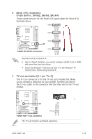
11. GAME/MIDI port connector (16-1 pin GAME) This connector is for a GAME/MIDI port. Connect the USB/GAME module cable to this connector, then install the module to a slot opening at the back of the system chassis. The GAME/MIDI port connects a joystick or game pad for playing games, and MIDI devices for playing or editing audio files. +5V J2B1 J2CX MIDI_OUT J2CY J2B2 MIDI_IN P5RD1-V ® P4RD1-MX GAME connector GAME The USB/GAME module is purchased separately. +5V J1B1 J1CX GND GND J1CY J1B2 +5V 12. Front panel audio connector (10-1 pin AAFP) This connector is for a chassis-mounted front panel audio I/O module that supports either HD Audio or legacy AC ʻ97 audio standard. Connect one end of the front panel audio I/O module cable to this connector. AAFP Azalia Legacy AC 97 compliant definition compliant definition AGND +5VA BLINE_OUT_R BLINE_OUT_L GND PRESENCE# SENSE1_RETUR SENSE2_RETUR P4RD1-MX ® MIC2 MICPWR Line out_R NC Line out_L PORT1 L PORT1 R PORT2 R SENSE_SEND PORT2 L P4RD1-MX Analog front panel connector • Connect a high-definiton front panel audio module to this connector to avail the high-definition audio features of the motherboard. • By default, this connector is set to legacy ACʼ97 audio. If you want to connect a high-definition front panel audio module to this connector, enable the HD Audio Controller item in the BIOS. ASUS P4RD1-MX 1-27
-
 1
1 -
2
-
3
-
4
-
5
-
6
-
7
-
8
-
9
-
10
-
11
-
12
-
13
-
14
-
15
-
16
-
17
-
18
-
19
-
20
-
21
-
22
-
23
-
24
-
25
-
26
-
27
-
28
-
29
-
30
-
31
-
32
-
33
-
 34
34 -
 35
35 -
 36
36 -
 37
37 -
 38
38 -
 39
39 -
 40
40 -
 41
41 -
 42
42 -
 43
43 -
 44
44 -
45
-
46
-
47
-
48
-
49
-
50
-
51
-
52
-
53
-
54
-
55
-
56
-
57
-
58
-
59
-
60
-
61
-
62
-
63
-
64
-
65
-
66
-
67
-
68
-
69
-
70
-
71
-
72
-
73
-
74
-
75
-
76
-
77
-
78
-
79
-
80
-
81
-
82
 |
 |
