Asus P5GPL-X SE Motherboard Installation Guide
Asus P5GPL-X SE Manual
 |
View all Asus P5GPL-X SE manuals
Add to My Manuals
Save this manual to your list of manuals |
Asus P5GPL-X SE manual content summary:
- Asus P5GPL-X SE | Motherboard Installation Guide - Page 1
P5GPL-X SE Motherboard - Asus P5GPL-X SE | Motherboard Installation Guide - Page 2
express written permission of ASUSTeK COMPUTER INC. ("ASUS"). Product warranty or service will not be extended if: (1) the ASUS HAS BEEN ADVISED OF THE POSSIBILITY OF SUCH DAMAGES ARISING FROM ANY DEFECT OR ERROR IN THIS MANUAL OR PRODUCT. SPECIFICATIONS AND INFORMATION CONTAINED IN THIS MANUAL - Asus P5GPL-X SE | Motherboard Installation Guide - Page 3
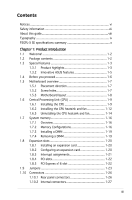
vii About this guide viii Typography ix P5GPL-X SE specifications summary x Chapter 1: Product introduction 1.1 Welcome 1-2 1.2 Package contents 1-2 1.3 Special features 1-3 1.3.1 Product highlights 1-3 1.3.2 Innovative ASUS features 1-5 1.4 Before you proceed 1-6 1.5 Motherboard overview - Asus P5GPL-X SE | Motherboard Installation Guide - Page 4
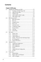
utility 2-4 2.1.4 ASUS CrashFree BIOS 2 utility 2-6 2.1.5 ASUS Update utility 2-8 2.2 BIOS setup program 2-11 2.2.1 BIOS menu screen 2-12 2.2.2 Menu bar 2-12 2.2.3 Navigation keys 2-12 2.2.4 Menu items 2-13 2.2.5 Sub-menu items 2-13 2.2.6 Configuration fields 2-13 2.2.7 Pop-up window 2-13 - Asus P5GPL-X SE | Motherboard Installation Guide - Page 5
support 3.1 Installing an operating system 3-2 3.2 Support CD information 3-2 3.2.1 Running the support CD 3-2 3.2.2 Drivers menu 3-3 3.2.3 Utilities menu 3-4 3.2.4 ASUS Contact information 3-5 Appendix: CPU features A.1 Intel® EM64T A-2 Using the Intel® EM64T feature A-2 A.2 Enhanced Intel - Asus P5GPL-X SE | Motherboard Installation Guide - Page 6
. This equipment generates, uses and can radiate radio frequency energy and, if not installed and used in accordance with manufacturer's instructions, may cause harmful interference to radio communications. However, there is no guarantee that interference will not occur in a particular installation - Asus P5GPL-X SE | Motherboard Installation Guide - Page 7
qualified service technician or your retailer. Operation safety • Before installing the motherboard and adding devices on it, carefully read all the manuals stable surface. • If you encounter technical problems with the product, contact a qualified service technician or your retailer. The symbol of - Asus P5GPL-X SE | Motherboard Installation Guide - Page 8
the BIOS parameters are also provided. • Chapter 3: Software support This chapter describes the contents of the support CD that comes with the motherboard package. Where to find more information Refer to the following sources for additional information and for product and software updates. 1. ASUS - Asus P5GPL-X SE | Motherboard Installation Guide - Page 9
following symbols used throughout this manual. DANGER/WARNING: Information to prevent injury to yourself when trying to complete a task. CAUTION: Information to prevent damage to the components when trying to complete a task. IMPORTANT: Instructions that you MUST follow to complete - Asus P5GPL-X SE | Motherboard Installation Guide - Page 10
P5GPL-X SE specifications summary CPU Chipset Front Side Bus Memory Expansion slots Storage A u d i o L A N USB Special features BIOS features Rear Panel LGA775 socket for Intel® Pentium® 4/Celeron® processors Supports Intel® single-core 65nm Intel® Pentium® 4/ - Asus P5GPL-X SE | Motherboard Installation Guide - Page 11
P5GPL-X SE specifications summary O v e r c l o c k i n g Internal c o n n e c t o r s Hardware monitoring Power Requirement Form Factor M a n a g e a b i l i t y Support CD c o n t e n t s ASUS CPU Lock Free Technology ASUS AI Overclocking (Intelligent CPU frequency tuner) - Asus P5GPL-X SE | Motherboard Installation Guide - Page 12
xii - Asus P5GPL-X SE | Motherboard Installation Guide - Page 13
This chapter describes the motherboard features and the new technologies it supports. 1Product introduction ASUS P5GPL-X SE 1-13 - Asus P5GPL-X SE | Motherboard Installation Guide - Page 14
for the following items. Motherboard ASUS P5GPL-X SE motherboard Cables 1 x Serial ATA signal cables 1 x Serial ATA power cables 1 x Ultra DMA cables 1 x Floppy disk drive cable Accessories I/O shield Application CDs ASUS motherboard support CD Documentation User guide If any of the - Asus P5GPL-X SE | Motherboard Installation Guide - Page 15
PDIF digital sound ready The motherboard supports the S/PDIF Out function through the midboard S/PDIF interface. The S/PDIF technology turns your computer into a highend entertainment system with digital connectivity to powerful audio and speaker systems. See pages 1-33 for details. ASUS P5GPL-X SE - Asus P5GPL-X SE | Motherboard Installation Guide - Page 16
and the Intel® ICH6. The SATA specification allows for thinner, more flexible cables with lower pin count, reduced voltage requirement, and up to 150 MB/s data transfer rate. Gigabit LAN support This motherboard comes with a Gigabit LAN controller to meet your growing networking needs. The - Asus P5GPL-X SE | Motherboard Installation Guide - Page 17
. With this utility, you can easily monitor the condition of the Ethernet cable(s) connected to the Marvell LAN (RJ-45) port. During the bootup process, AI NET 2 immediately diagnoses the LAN cable and can report shorts and faults up to 100 meters away at 1 meter accuracy. ASUS P5GPL-X SE 1-17 - Asus P5GPL-X SE | Motherboard Installation Guide - Page 18
you should shut down the system and unplug the power cable before removing or plugging in any motherboard component. The illustration below shows the location of the onboard LED. P5GPL-X ® SB_PWR ON P5GPL-X SE Onboard LED Standby Power OFF Powered Off 1-18 Chapter 1: Product introduction - Asus P5GPL-X SE | Motherboard Installation Guide - Page 19
indicated in the image below. 1.5.2 Screw holes Place seven (7) screws into the holes indicated by circles to secure the motherboard to the chassis. Do not overtighten the screws! Doing so can damage the motherboard. Place this side towards the rear of the chassis P5GPL-X SE ® ASUS P5GPL-X SE 1-19 - Asus P5GPL-X SE | Motherboard Installation Guide - Page 20
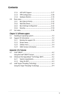
Motherboard layout 18.2cm (7.2in) PS/2KBMS T: Mouse B: Keyboard KBPWR SPDIF_O ATX12V LGA775 PARALLEL PORT COM1 F_USB12 LAN_USB34 Top:Line In Center:Line Out Below:Mic In USBPW1 Intel® 915PL CHA_FAN CPU_FAN Super I/O Marvell 88E8001 P5GPL-X SE PCIEX16 ® PCI1 PCI2 Intel® ICH6 Intel - Asus P5GPL-X SE | Motherboard Installation Guide - Page 21
Unit (CPU) The motherboard comes with a surface mount LGA775 socket designed for the Intel® Pentium® 4 processor in the 775-land package. • Your boxed Intel® Pentium® 4 LGA775 processor package should come with installation instructions for the CPU, fan and heatsink assembly. If the instructions in - Asus P5GPL-X SE | Motherboard Installation Guide - Page 22
. 4. Lift the load plate with your thumb and forefinger to a 100º angle (A), then push the PnP cap from the load plate window to remove (B). B A Load plate 5. Position the CPU over the socket, making sure that the gold triangle is on the bottom‑left corner of the socket. The socket alignment key - Asus P5GPL-X SE | Motherboard Installation Guide - Page 23
6. Close the load plate (A), then A push the load lever (B) until it snaps into the retention tab. B The CPU fits in only one correct orientation. DO NOT force the CPU into the socket to prevent bending the connectors on the socket and damaging the CPU! ASUS P5GPL-X SE 1-23 - Asus P5GPL-X SE | Motherboard Installation Guide - Page 24
The Intel® Pentium® 4 LGA775 processor requires a specially designed heatsink and fan assembly to ensure optimum thermal condition and performance. • Install the motherboard to the chassis before you install the CPU fan and heatsink assembly • When you buy a boxed Intel® Pentium® 4 processor, the - Asus P5GPL-X SE | Motherboard Installation Guide - Page 25
the CPU fan cable to the connector on the motherboard labeled CPU_FAN. GND CPU FAN PWR CPU FAN IN CPU FAN PWM P5GPL-X ® CPU_FAN P5GPL-X SE CPU fan connector Do not forget to connect the CPU fan connector! Hardware monitoring errors can occur if you fail to plug this connector. ASUS P5GPL-X SE - Asus P5GPL-X SE | Motherboard Installation Guide - Page 26
1.6.3 Uninstalling the CPU heatsink and fan To uninstall the CPU heatsink and fan: 1. Disconnect the CPU fan cable from the connector on the motherboard. 2. Rotate each fastener counterclockwise. 3. Pull up two fasteners at a time in a diagonal sequence to disengage the heatsink B and fan - Asus P5GPL-X SE | Motherboard Installation Guide - Page 27
4. Remove the heatsink and fan assembly from the motherboard. 5. Rotate each fastener clockwise to reset the orientation. When reset, each fastener should be oriented as shown, with the narrow groove directed outward. ASUS P5GPL-X SE 1-27 - Asus P5GPL-X SE | Motherboard Installation Guide - Page 28
motherboard comes with two 184-pin Double Data Rate (DDR) Dual Inline Memory Modules (DIMM) sockets. The following figure illustrates the location of the sockets: P5GPL-X ® P5GPL-X SE sizing error or system boot failure. Use any of supported in this motherboard. 1-28 Chapter 1: Product introduction - Asus P5GPL-X SE | Motherboard Installation Guide - Page 29
Qualified Vendors List Size Vendor Model Brand Side(s) Component DIMM support A B 257MB 258MB 256MB 512MB 512MB 1024MB 1024MB 256MB 256MB V V NT5DS32M16BT-5T V V NT5DS64M8BT-5T V V NT5DS3232M8BT-5T V V NT5DS32M8CT-5T V V (Continued on the next page) ASUS P5GPL-X SE 1-17 - Asus P5GPL-X SE | Motherboard Installation Guide - Page 30
W9425GCDB-5 DDR400 Winbond SS W942508CH-5 V V 512MB Winbond W9451GCDB-5 DDR400 Winbond DS W942508CH-5 V V Legend: A - supports one module inserted into either slot, in a Single-channel memory configuration. B - supports one pair of modules inserted into two slots as one pair of Dual-channel - Asus P5GPL-X SE | Motherboard Installation Guide - Page 31
to do so may cause severe damage to both the motherboard and the components. 1. Unlock a DIMM socket by Support the DIMM lightly with your fingers when pressing the retaining clips. The DIMM might get damaged when it flips out with extra force. 2. Remove the DIMM from the socket. ASUS P5GPL-X SE - Asus P5GPL-X SE | Motherboard Installation Guide - Page 32
the expansion cards that they support. Make sure to unplug the physical injury and damage motherboard components. 1.8.1 Installing Remove the system unit cover (if your motherboard is already installed in a chassis). 3. the necessary BIOS settings, if any. See Chapter 2 for information on BIOS setup. - Asus P5GPL-X SE | Motherboard Installation Guide - Page 33
- - - - - - - - - used When using PCI cards on shared slots, ensure that the drivers support "Share IRQ" or that the cards do not need IRQ assignments. Otherwise, conflicts will arise between the two PCI groups, making the system unstable and the card inoperable. ASUS P5GPL-X SE 1-21 - Asus P5GPL-X SE | Motherboard Installation Guide - Page 34
1.8.4 PCI slots The PCI slots support cards such as a LAN card, SCSI card, USB card, and other cards that comply with PCI specifications. The figure shows a LAN card installed on a PCI slot. 1.8.5 PCI Express x16 slot This motherboard supports PCI Express x16 graphic cards that comply with the PCI - Asus P5GPL-X SE | Motherboard Installation Guide - Page 35
RAM setting You do not need to clear the RTC when the system hangs due to overclocking. For system failure due to overclocking, use the C.P.R. (CPU Parameter Recall) feature. Shut down and reboot the system so the BIOS can automatically reset parameter settings to default values. ASUS P5GPL-X SE - Asus P5GPL-X SE | Motherboard Installation Guide - Page 36
CPU, DRAM in slow refresh, power supply in reduced power mode). The USBPW1 jumpers are for the rear USB ports. The USBPW2 jumper is for the internal USB connectors that you can connect to additional USB ports. USBPW1 2 1 +5V (Default) 3 2 +5VSB P5GPL-X ® USBPW2 12 23 +5V (Default) P5GPL-X SE - Asus P5GPL-X SE | Motherboard Installation Guide - Page 37
the Space Bar). This feature requires an ATX power supply that can supply at least 1A on the +5VSB lead, and a corresponding setting in the BIOS. P5GPL-X ® KBPWR 2 1 +5V (Default) 3 2 +5VSB P5GPL-X SE Keyboard power setting ASUS P5GPL-X SE 1-25 - Asus P5GPL-X SE | Motherboard Installation Guide - Page 38
to a Local Area Network (LAN) through a network hub. Refer to the table below for the LAN port LED indications. LAN port LED indications ACT/ microphone. Refer to the audio configuration table for the function of the audio ports in 2, 4, or 6-channel configuration. Audio 2, 4, or 6-channel - Asus P5GPL-X SE | Motherboard Installation Guide - Page 39
USB) ports are available for connecting USB 2.0 devices. 8. USB 2.0 ports 1 and 2. These two 4-pin Universal Serial Bus (USB) ports are available for connecting USB 2.0 devices. 9. Coaxial S/PDIF Out port. This port connects an external audio P5GPL-X ® P5GPL-X SE IDE connector ASUS P5GPL-X SE 1-27 - Asus P5GPL-X SE | Motherboard Installation Guide - Page 40
1. P5GPL-X SE Floppy disk drive connector 3. CPU and chassis fan connectors (4-pin CPU_FAN, 3-pin CHA_FAN) The fan connectors support cooling fans of 350mA~2000mA (24W max.) or a total of 1A~3.48A (41.36W max.) at +12V. Connect the fan cables to the fan connectors on the motherboard, making - Asus P5GPL-X SE | Motherboard Installation Guide - Page 41
GND RSATA_RXP1 RSATA_RXN1 GND SATA1 P5GPL-X SE SATA connectors Important notes on Serial ATA • Install the Windows® 2000 Service Pack 4 or the Windows® XP Service Pack1 before using Serial ATA. • Plug your Serial ATA boot disk on the master port (SATA1 and SATA2) to support S3 function. Refer to - Asus P5GPL-X SE | Motherboard Installation Guide - Page 42
of the system chassis. USB+5V USB_P8USB_P8+ GND NC USB+5V USB_P6USB_P6+ GND NC P5GPL-X ® USB56 1 P5GPL-X SE USB 2.0 connectors USB78 1 USB+5V USB_P7USB_P7+ GND USB+5V USB_P5USB_P5+ GND Never connect a 1394 cable to the USB connectors. Doing so will damage the motherboard! USB/Game module is - Asus P5GPL-X SE | Motherboard Installation Guide - Page 43
Right Audio Channel Ground Ground Left Audio Channel 7. Optical drive audio connector (4-pin CD) This connector is for the 4-pin audio cable that connects to the audio connector at the back of the optical drive. P5GPL-X ® CD P5GPL-X SE CD audio connector ASUS P5GPL-X SE 1-31 - Asus P5GPL-X SE | Motherboard Installation Guide - Page 44
boot up if the power is inadequate. • The ATX 12 V Specification 2.0-compliant PSU passed the motherboard power requirement test with the following configuration: CPU Power OK P5GPL-X GND +12V DC Ground +5 Volts ® Ground +5 Volts Ground +3 Volts P5GPL-X SE ATX power connectors - Asus P5GPL-X SE | Motherboard Installation Guide - Page 45
for the S/PDIF audio module to allow digital sound output. Connect one end of the S/PDIF audio cable to this connector and the other end to the S/PDIF module. +5V SPDIFOUT GND P5GPL-X ® SPDIF_OUT P5GPL-X SE Digital audio connector The S/PDIF module is purchased separately. ASUS P5GPL-X SE 1-33 - Asus P5GPL-X SE | Motherboard Installation Guide - Page 46
connector supports several chassis-mounted functions. PLED SPEAKER PLED+ PLED+5V Ground Ground Speaker P5GPL-X ® PANEL IDE_LED P5GPL-X SE System ON or puts the system in SLEEP or SOFT-OFF mode depending on the BIOS settings. Pressing the power switch for more than four seconds while the system - Asus P5GPL-X SE | Motherboard Installation Guide - Page 47
This chapter tells how to change the system settings through the BIOS Setup menus. Detailed descriptions of the BIOS parameters are also provided. 2 BIOS setup ASUS P5GPL-X SE 2-35 - Asus P5GPL-X SE | Motherboard Installation Guide - Page 48
floppy disk.) 2. ASUS EZ Flash (Updates the BIOS using a floppy disk during POST.) 3. ASUS CrashFree BIOS 2 (Updates the BIOS using a bootable floppy disk or the motherboard support CD when the BIOS file fails or gets corrupted.) 4. ASUS Update (Updates the BIOS in Windows® environment.) Refer to - Asus P5GPL-X SE | Motherboard Installation Guide - Page 49
system boot failure! • A "Floppy not found!" error message appears if there is no floppy disk in the drive. A "P5GPLXS.ROM not found!" error message appears if the correct BIOS file is not found in the floppy disk. Make sure that you rename the BIOS file to P5GPLXS.ROM. ASUS P5GPL-X SE 2-37 - Asus P5GPL-X SE | Motherboard Installation Guide - Page 50
to save the file. • The succeeding BIOS screens are for reference only. The actual BIOS screen displays may not be exactly the same as shown. 1. Copy the AFUDOS utility (afudos.exe) from the motherboard support CD to the bootable floppy disk you created earlier. 2. Boot the system in DOS mode, then - Asus P5GPL-X SE | Motherboard Installation Guide - Page 51
Updating the BIOS file To update the BIOS file using the AFUDOS utility: 1. Visit the ASUS website (www.asus.com) and download the latest BIOS file for the motherboard. Save the BIOS file to a bootable floppy disk. Write the BIOS filename on a piece of paper. You need to type the exact BIOS filename - Asus P5GPL-X SE | Motherboard Installation Guide - Page 52
disk that contains the updated BIOS file. • Prepare the motherboard support CD or the floppy disk containing the updated motherboard BIOS before using this utility. • Make sure that you rename the original or updated BIOS file in the floppy disk to P5GPLXS.ROM. Recovering the BIOS from a floppy disk - Asus P5GPL-X SE | Motherboard Installation Guide - Page 53
updating the BIOS! Doing so can cause system boot failure! 4. Restart the system after the utility completes the updating process. The recovered BIOS may not be the latest BIOS version for this motherboard. Visit the ASUS website (www.asus.com) to download the latest BIOS file. ASUS P5GPL-X SE - Asus P5GPL-X SE | Motherboard Installation Guide - Page 54
CD that comes with the motherboard package. ASUS Update requires an Internet connection either through a network or an Internet Service Provider (ISP). Installing ASUS Update To install ASUS Update: 1. Place the support CD in the optical drive. The Drivers menu appears. 2. Click the Utilities - Asus P5GPL-X SE | Motherboard Installation Guide - Page 55
> Programs > ASUS > ASUSUpdate > ASUSUpdate. The ASUS Update main window appears. 2. Select Update BIOS from the Internet option from the drop‑down menu, then click Next. 3. Select the ASUS FTP site nearest you to avoid network traffic, or click Auto Select. Click Next. ASUS P5GPL-X SE 2-43 - Asus P5GPL-X SE | Motherboard Installation Guide - Page 56
to download. Click Next. 5. Follow the screen instructions to complete the update process. The ASUS Update utility is capable of updating itself through the Internet. Always update the utility to avail all its features. Updating the BIOS through a BIOS file To update the BIOS through a BIOS file - Asus P5GPL-X SE | Motherboard Installation Guide - Page 57
Exit Menu. See section "2.7 Exit Menu." • The BIOS setup screens shown in this section are for reference purposes only, and may not exactly match what you see on your screen. • Visit the ASUS website (www.asus.com) to download the latest BIOS file for this motherboard and . ASUS P5GPL-X SE 2-11 - Asus P5GPL-X SE | Motherboard Installation Guide - Page 58
advanced system settings For changing the advanced power management (APM) configuration For changing the system boot configuration For selecting the exit options and loading default settings To select an item on the the navigation keys differ from one screen to another. 2-12 Chapter 2: BIOS setup - Asus P5GPL-X SE | Motherboard Installation Guide - Page 59
item on the menu bar displays the specific items for that menu. For example, selecting Main shows the Main menu items. The other items (Advanced, Power, Boot, and Exit) on the menu bar have +- Change Option F1 General Help F10 Save and Exit ESC Exit Pop-up window Scroll bar ASUS P5GPL-X SE 2-13 - Asus P5GPL-X SE | Motherboard Installation Guide - Page 60
screen appears, giving you an overview of the basic system information. Refer to section "2.2.1 BIOS menu screen" for information on the menu screen items and how to navigate through them. , 5.25 in.] [1.2M , 5.25 in.] [720K , 3.5 in.] [1.44M, 3.5 in.] [2.88M, 3.5 in.] 2-14 Chapter 2: BIOS setup - Asus P5GPL-X SE | Motherboard Installation Guide - Page 61
the BIOS automatically type. Select CDROM if you are specifically configuring a CD-ROM drive. Select supports multi-sector transfer feature. When set to [Disabled], the data transfer from and to the device occurs one sector at a time. Configuration options: [Disabled] [Auto] ASUS P5GPL-X SE - Asus P5GPL-X SE | Motherboard Installation Guide - Page 62
the system. Select an item then press if you wish to configure the item. IDE Configuration Onboard IDE Operate Mode [Enhanced Mode] Enhanced Mode Support On [S-ATA] IDE Detect Time Out (Sec) [35] 2-16 Chapter - Asus P5GPL-X SE | Motherboard Installation Guide - Page 63
native OS including Windows® 2000/XP. Configuration options: [Disabled] [Compatible Mode] [Enhanced Mode] Enhanced Mode Support On [S-ATA . If you set to any of these options and encounter problems, revert to the default setting [Secondary P-ATA+S-ATA]. Configuration 30] [35] ASUS P5GPL-X SE 2-17 - Asus P5GPL-X SE | Motherboard Installation Guide - Page 64
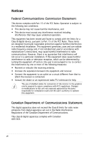
Version : 0106 Build Date : 01/06/06 Processor Type Speed Count : Genuine Intel(R) CPU 3.20GHz : 3200 MHz : 1 System Memory Size : 512MB AMI BIOS Displays the auto-detected BIOS information Processor Displays the auto-detected CPU specification System Memory Displays the auto-detected system - Asus P5GPL-X SE | Motherboard Installation Guide - Page 65
USB Configuration CPU Configuration Chipset Onboard Devices Configuration PCI PnP Configure CPU CPU overclocking options to achieve desired CPU internal frequency. Select either one of the preset overclocking configuration options: Manual [FSB900/DDR1-450] [FSB1000/DDR1-500] ASUS P5GPL-X SE 2-19 - Asus P5GPL-X SE | Motherboard Installation Guide - Page 66
to [Auto] allows the motherboard to automatically reduce the CPU multiplier value for more flexibility when increasing the external FSB. Configuration options: [Auto] [Disabled] [Enabled] This function works with Intel® Prescott-cored 6xx series Pentium® 4 CPU. PCI Clock Synchronization Mode - Asus P5GPL-X SE | Motherboard Installation Guide - Page 67
] Allows you to enable or disable the USB 2.0 controller. Configuration options: [Disabled] [Enabled] USB 2.0 Controller Mode [HiSpeed] Allows you to configure the USB 2.0 controller in HiSpeed (480 Mbps) or Full Speed (12 Mbps). Configuration options: [HiSpeed] [Full Speed] ASUS P5GPL-X SE 2-21 - Asus P5GPL-X SE | Motherboard Installation Guide - Page 68
This item appears only when you install a processor with CPU Lock Free feature. Configuration options: [Auto] [Disabled] [Enabled] Max CPUID Value Limit [Disabled] Enable this item to boot legacy operating systems that cannot support CPUs with extended CPUID functions. Configuration options - Asus P5GPL-X SE | Motherboard Installation Guide - Page 69
processor Hyper-Threading Technology. Configuration options: [Disabled] [Enabled] The following item appears only when you installed an Intel® Pentium® 4 CPU that supports the Enhanced Intel SpeedStep® Technology (EIST). Intel The motherboard comes with a BIOS file that supports ASUS P5GPL-X SE Select - Asus P5GPL-X SE | Motherboard Installation Guide - Page 70
DRAM SPD (Serial Presence Detect). When disabled, you can manually set the DRAM timing parameters through the DRAM sub-items. Allows selection of the graphics controller to use as primary boot device. Configuration options: [PCI Express/PCI] [PCI/PCI ] [Fast] [Faster] 2-24 Chapter 2: BIOS setup - Asus P5GPL-X SE | Motherboard Installation Guide - Page 71
2.4.5 Onboard Devices Configuration Configure Win627EHF Super IO Chipset HD Audio Controller [Enabled] Onboard LAN [Enabled] LAN Option ROM [Disabled] Serial Port1 Address [3F8/IRQ4] Parallel Port mode. Configuration options: [Normal] [Bi-directional] [EPP] [ECP] ASUS P5GPL-X SE 2-25 - Asus P5GPL-X SE | Motherboard Installation Guide - Page 72
[PCI Device] Select Screen Select Item +- Change Option F1 General Help F10 Save and Exit ESC Exit Plug and Play O/S [No] When set to [No], BIOS configures all the devices in the system. When set to [Yes] and if you install a Plug and Play operating system, the operating system configures the - Asus P5GPL-X SE | Motherboard Installation Guide - Page 73
to [PCI Device] When set to [PCI Device], the specific IRQ is free for use of PCI/PnP devices. When ACPI 2.0 Support [No] ACPI APIC Support [Enabled] APM Configuration Hardware Monitor Configure CPU. Select BIOS POST on S3/STR resume. Configuration options: [No] [Yes] ASUS P5GPL-X SE 2-27 - Asus P5GPL-X SE | Motherboard Installation Guide - Page 74
the Advanced Configuration and Power Interface (ACPI) support in the Application-Specific Integrated Circuit (ASIC). When set to Off] Resume On RTC Alarm [Disabled] Resume On By External Modems [Disabled] Resume On By PCI/PCIEX Devices [Disabled] Power On ~ [31] 2-28 Chapter 2: BIOS setup - Asus P5GPL-X SE | Motherboard Installation Guide - Page 75
connection cannot be made on the first try. Turning an external modem off and then back on while the computer is off causes an [Enabled] Power On By PS/2 Keyboard [Disabled] Allows you to use specific keys on the keyboard to turn on the system. This feature requires an ] ASUS P5GPL-X SE 2-29 - Asus P5GPL-X SE | Motherboard Installation Guide - Page 76
in rotations per minute (RPM). If the fan is not connected to the motherboard, the field shows N/A. Configuration options: [Ignored] [xxxC/xxxF] [N/A] CPU Q-Fan Control [Disabled] Allows you to enable or disable the ASUS Q-Fan feature that smartly adjusts the fan speeds for more efficient system - Asus P5GPL-X SE | Motherboard Installation Guide - Page 77
items allow you to change the system boot options. Select an item then press to display the sub-menu. APM Configuration Boot Device Priority Boot Settings Configuration Security Select Screen Select Item Enter Go to Sub-screen F1 General Help F10 Save and Exit ESC Exit ASUS P5GPL-X SE 2-31 - Asus P5GPL-X SE | Motherboard Installation Guide - Page 78
]a[SlDubHi-esslacpbrleeedn] F10 Save and Exit ESC Exit 2.6.3 Boot Settings Configuration Boot Settings Configuration Quick Boot [Enabled] Full Screen Logo [Enabled] AddOn ROM Display Mode [Force BIOS] Bootup Num-Lock [On] PS/2 Mouse Support [Auto] Wait For 'F1' If Error [Enabled] Hit - Asus P5GPL-X SE | Motherboard Installation Guide - Page 79
BIOS] [Keep Current] Bootup Num-Lock [On] Allows you to select the power-on state for the NumLock. Configuration options: [Off] [On] PS/2 Mouse Support [Auto] Allows you to enable or disable support option ROMs to trap Interrupt 19. Configuration options: [Disabled] [Enabled] ASUS P5GPL-X SE 2-33 - Asus P5GPL-X SE | Motherboard Installation Guide - Page 80
the supervisor password, select the Change Supervisor Password then press . The message "Password Uninstalled" appears. If you forget your BIOS password, you can clear clear it by erasing the CMOS Real Time Clock (RTC) RAM. See section "1.9 Jumpers" for information on how to erase the RTC - Asus P5GPL-X SE | Motherboard Installation Guide - Page 81
. The message "Password Installed" appears after you set your password successfully. To change the user password, follow the same steps as in setting a user password. ASUS P5GPL-X SE 2-35 - Asus P5GPL-X SE | Motherboard Installation Guide - Page 82
Setup utility. When set to [Always], BIOS checks for user password both when accessing Setup and booting the system. Configuration options: [Setup] [ RAM. An onboard backup battery sustains the CMOS RAM so it stays on even when the PC is turned off. When you select this option, a confirmation window - Asus P5GPL-X SE | Motherboard Installation Guide - Page 83
fields other than System Date, System Time, and Password, the BIOS asks for a confirmation before exiting. Discard Changes This option window appears. Select Ok to load default values. Select Exit & Save Changes or make other changes before saving the values to the non-volatile RAM. ASUS P5GPL-X SE - Asus P5GPL-X SE | Motherboard Installation Guide - Page 84
2-38 Chapter 2: BIOS setup - Asus P5GPL-X SE | Motherboard Installation Guide - Page 85
This chapter describes the contents of the support CD that comes with the motherboard package. 3 Software support ASUS P5GPL-X SE 3-39 - Asus P5GPL-X SE | Motherboard Installation Guide - Page 86
that you install Windows® 2000 Service Pack 4 or the Windows® XP Service Pack 1 or later versions before installing the drivers for better compatibility and system stability. 3.2 Support CD information The support CD that came with the motherboard package contains the drivers, software applications - Asus P5GPL-X SE | Motherboard Installation Guide - Page 87
that came with the utility for details. SoundMAX Audio Driver Executes the wizard to install the ADI AD1986A SoundMAX audio driver and application. Marvell Yukon Gigabit Ethernet Driver Installs the Marvell® Gigabit Ethernet driver. USB 2.0 Driver Installs the USB 2.0 driver. ASUS P5GPL-X SE 3-41 - Asus P5GPL-X SE | Motherboard Installation Guide - Page 88
detected problems. This utility helps you keep your computer in healthy operating condition. ASUS Update The ASUS Update utility allows you to update the motherboard BIOS in a Windows® environment. This utility requires an Internet connection either through a network or an Internet Service Provider - Asus P5GPL-X SE | Motherboard Installation Guide - Page 89
® Acrobat® Reader from the Utilities menu before opening a user manual file. Intel LGA775 CPU install User's Manual Allows you to open the Intel LGA775 CPU install user's manual. P5GPL-X SE Motherboard User's Manual Allows you to open the P5GPL-X SE Motherboard user's manual. ASUS P5GPL-X SE 3-43 - Asus P5GPL-X SE | Motherboard Installation Guide - Page 90
3.2.5 ASUS Contact information Click the Contact tab to display the ASUS contact information. You can also find this information on the inside front cover of this user guide. 3-44 Chapter 3: Software support - Asus P5GPL-X SE | Motherboard Installation Guide - Page 91
The Appendix describes the CPU features that the motherboard supports. CPU A features - Asus P5GPL-X SE | Motherboard Installation Guide - Page 92
fully compatible with Intel® Pentium® 4 LGA775 processors running on 32-bit operating systems. • The motherboard comes with a BIOS file that supports EM64T. You can download the latest BIOS file from the ASUS website (www.asus. com/support/download/) if you need to update the BIOS file. See Chapter - Asus P5GPL-X SE | Motherboard Installation Guide - Page 93
or Always On. 9. Click Apply, then click OK. 10. Close the Display Properties window. After you adjust the power scheme, the CPU internal frequency slightly decreases when the CPU loading is low. The screen displays and procedures may vary depending on the operating system. ASUS P5GPL-X SE A-3 - Asus P5GPL-X SE | Motherboard Installation Guide - Page 94
The motherboard supports Intel® Pentium® 4 LGA775 processors with Hyper-Threading Technology. • Hyper-Threading Technology is supported under Windows® XP/2003 : 1. Install an Intel® Pentium® 4 CPU that supports Hyper-Threading Technology. 2. Power up the system and enter the BIOS Setup. Under the
-
 1
1 -
 2
2 -
 3
3 -
 4
4 -
 5
5 -
 6
6 -
 7
7 -
8
-
9
-
10
-
11
-
12
-
13
-
14
-
15
-
16
-
17
-
18
-
19
-
20
-
21
-
22
-
23
-
24
-
25
-
26
-
27
-
28
-
29
-
30
-
31
-
32
-
33
-
34
-
35
-
36
-
37
-
38
-
39
-
40
-
41
-
42
-
43
-
44
-
45
-
46
-
47
-
48
-
49
-
50
-
51
-
52
-
53
-
54
-
55
-
56
-
57
-
58
-
59
-
60
-
61
-
62
-
63
-
64
-
65
-
66
-
67
-
68
-
69
-
70
-
71
-
72
-
73
-
74
-
75
-
76
-
77
-
78
-
79
-
80
-
81
-
82
-
83
-
84
-
85
-
86
-
87
-
88
-
89
-
90
-
91
-
92
-
93
-
94
 |
 |

Motherboard
P5GPL-X SE