Asus P5W64 WS PRO Motherboard Installation Guide - Page 54
Serial ATA hard disk drive connection - motherboard manual
 |
View all Asus P5W64 WS PRO manuals
Add to My Manuals
Save this manual to your list of manuals |
Page 54 highlights
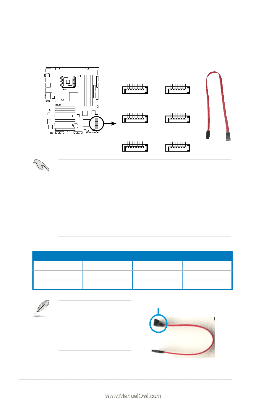
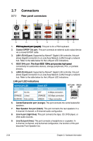
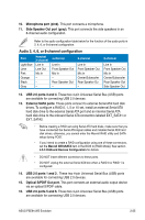
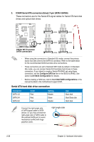
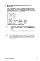
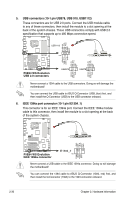
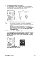
3. ICH9R Serial ATA connectors [blue] (7-pin SATA1-SATA6) These connectors are for the Serial ATA signal cables for Serial ATA hard disk drives and optical disk drives. GND RSATA_TXP1 RSATA_TXN1 GND RSATA_RXP1 RSATA_RXN1 GND GND RSATA_TXP2 RSATA_TXN2 GND RSATA_RXP2 RSATA_RXN2 GND ® P5E64 WS EVOLUTION R P5B GND RSATA_TXP3 RSATA_TXN3 GND RSATA_RXP3 RSATA_RXN3 GND GND RSATA_RXN1 RSATA_RXP1 GND RSATA_TXN1 RSATA_TXP1 GND GND RSATA_RXN2 RSATA_RXP2 GND RSATA_TXN2 RSATA_TXP2 GND SATA1 SATA2 SATA2 SATA1 GND RSATA_TXP4 RSATA_TXN4 GND RSATA_RXP4 RSATA_RXN4 GND SATA3 SATA3 SATA4 SATA4 GND RSATA_RXN3 RSATA_RXP3 GND RSATA_TXN3 RSATA_TXP3 GND GND RSATA_RXN4 RSATA_RXP4 GND RSATA_TXN4 RSATA_TXP4 GND GND RSATA_TXP5 RSATA_TXN5 GND RSATA_RXP5 RSATA_RXN5 GND GND RSATA_TXP6 RSATA_TXN6 GND RSATA_RXP6 RSATA_RXN6 GND P5E64 WS EvoPlu5tBioSnATA Connectors SATA connectors SATA6 SATA5 • When using the connectors in Standard IDE mode, connect the primary (boot) hard disk drive to the SATA1/2 connector. Refer to the table below for the recommended SATA hard disk drive connections. • These connectors are set to Standard IDE mode by default. In Standard IDE mode, you can connect Serial ATA boot/data hard drives to these connectors. If you intend to create a Serial ATA RAID set using these connectors, set the Configure SATA as item in the BIOS to [RAID]. See section 4.3.6 SATA Configuration for details. • Before creating a RAID set, refer to 5.4.3 Intel RAID configurations or the manual bundled in the motherboard support DVD. Serial ATA hard disk drive connection Connector SATA 1/2 SATA 3/4 SATA 5/6 Color Red Red Red Setting Master Slave Master Use Boot disk Boot/Data disk Boot disk Connect the right-angle side of SATA signal cable to SATA device. Or you may connect the right-angle side of SATA cable to the onboard SATA port to avoid mechanical conflict with huge graphics cards. right angle side 2-28 Chapter 2: Hardware information
-
 1
1 -
2
-
3
-
4
-
5
-
6
-
7
-
8
-
9
-
10
-
11
-
12
-
13
-
14
-
15
-
16
-
17
-
18
-
19
-
20
-
21
-
22
-
23
-
24
-
25
-
26
-
27
-
28
-
29
-
30
-
31
-
32
-
33
-
34
-
35
-
36
-
37
-
38
-
39
-
40
-
41
-
42
-
43
-
44
-
45
-
46
-
47
-
48
-
 49
49 -
 50
50 -
 51
51 -
 52
52 -
 53
53 -
 54
54 -
 55
55 -
 56
56 -
 57
57 -
 58
58 -
 59
59 -
60
-
61
-
62
-
63
-
64
-
65
-
66
-
67
-
68
-
69
-
70
-
71
-
72
-
73
-
74
-
75
-
76
-
77
-
78
-
79
-
80
-
81
-
82
-
83
-
84
-
85
-
86
-
87
-
88
-
89
-
90
-
91
-
92
-
93
-
94
-
95
-
96
-
97
-
98
-
99
-
100
-
101
-
102
-
103
-
104
-
105
-
106
-
107
-
108
-
109
-
110
-
111
-
112
-
113
-
114
-
115
-
116
-
117
-
118
-
119
-
120
-
121
-
122
-
123
-
124
-
125
-
126
-
127
-
128
-
129
-
130
-
131
-
132
-
133
-
134
-
135
-
136
-
137
-
138
-
139
-
140
-
141
-
142
-
143
-
144
-
145
-
146
-
147
-
148
-
149
-
150
-
151
-
152
-
153
-
154
-
155
-
156
-
157
-
158
-
159
-
160
-
161
-
162
-
163
-
164
-
165
-
166
-
167
-
168
-
169
-
170
-
171
-
172
-
173
-
174
-
175
-
176
-
177
-
178
-
179
-
180
 |
 |