Asus P5W64 WS PRO Motherboard Installation Guide - Page 93
CPU PLL Voltage [Auto], FSB Termination Voltage [Auto], DRAM Voltage [Auto], NB Voltage [Auto]
 |
View all Asus P5W64 WS PRO manuals
Add to My Manuals
Save this manual to your list of manuals |
Page 93 highlights
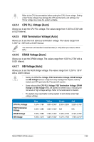
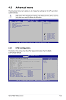
Refer to the CPU documentation before setting the CPU Vcore voltage. Setting a high VCore voltage may damage the CPU permanently, and setting a low VCore voltage may make the system unstable. 4.4.14 CPU PLL Voltage [Auto] Allows you to set the CPU PLL voltage. The values range from 1.50V to 2.78V with a 0.02V interval. 4.4.15 FSB Termination Voltage [Auto] Allows you to set the front side bus termination voltage. The values range from 1.20V* to 1.50V with a 0.02V interval. The minimum and standard value becomes [1.10V] when you install a 45nm CPU. 4.4.16 DRAM Voltage [Auto] Allows you to set the DRAM voltage. The values range from 1.50V to 2.78V with a 0.02V interval. 4.4.17 NB Voltage [Auto] Allows you to set the North Bridge voltage. The values range from 1.25V to 1.91V with a 0.02V interval. • Setting the CPU PLL Voltage, FSB Termination Voltage, DRAM Voltage and NB Voltage items to a high level may damage the chipset, memory module and CPU permanently. Proceed with caution. • Some values of the CPU PLL Voltage, FSB Termination Voltage, DRAM Voltage and NB Voltage items are labeled in different color, indicating the risk levels of high voltage settings. Refer to the table below for details. • The system may need better cooling system to work stably under high voltage settings. CPU PLL Voltage FSB Termination Voltage DRAM Voltage NB Voltage Blue Yellow Purple Red 1.50V~1.78V 1.80V~2.00V 2.02V~2.20V 2.22V~2.78V 1.20V~1.38V 1.40V~1.50V N/A N/A 1.50V~1.68V 1.70V~1.90V 1.92V~2.10V 2.12V~2.78V 1.25V~1.41V 1.43V~1.55V 1.57V~1.73V 1.75V~2.21V* ASUS P5E64 WS Evolution 4-23
-
 1
1 -
2
-
3
-
4
-
5
-
6
-
7
-
8
-
9
-
10
-
11
-
12
-
13
-
14
-
15
-
16
-
17
-
18
-
19
-
20
-
21
-
22
-
23
-
24
-
25
-
26
-
27
-
28
-
29
-
30
-
31
-
32
-
33
-
34
-
35
-
36
-
37
-
38
-
39
-
40
-
41
-
42
-
43
-
44
-
45
-
46
-
47
-
48
-
49
-
50
-
51
-
52
-
53
-
54
-
55
-
56
-
57
-
58
-
59
-
60
-
61
-
62
-
63
-
64
-
65
-
66
-
67
-
68
-
69
-
70
-
71
-
72
-
73
-
74
-
75
-
76
-
77
-
78
-
79
-
80
-
81
-
82
-
83
-
84
-
85
-
86
-
87
-
 88
88 -
 89
89 -
 90
90 -
 91
91 -
 92
92 -
 93
93 -
 94
94 -
 95
95 -
 96
96 -
 97
97 -
 98
98 -
99
-
100
-
101
-
102
-
103
-
104
-
105
-
106
-
107
-
108
-
109
-
110
-
111
-
112
-
113
-
114
-
115
-
116
-
117
-
118
-
119
-
120
-
121
-
122
-
123
-
124
-
125
-
126
-
127
-
128
-
129
-
130
-
131
-
132
-
133
-
134
-
135
-
136
-
137
-
138
-
139
-
140
-
141
-
142
-
143
-
144
-
145
-
146
-
147
-
148
-
149
-
150
-
151
-
152
-
153
-
154
-
155
-
156
-
157
-
158
-
159
-
160
-
161
-
162
-
163
-
164
-
165
-
166
-
167
-
168
-
169
-
170
-
171
-
172
-
173
-
174
-
175
-
176
-
177
-
178
-
179
-
180
 |
 |
