Asus P8B75-M LX PLUS P8B75-M LX PLUS User's Manual - Page 35
Internal connectors
 |
View all Asus P8B75-M LX PLUS manuals
Add to My Manuals
Save this manual to your list of manuals |
Page 35 highlights
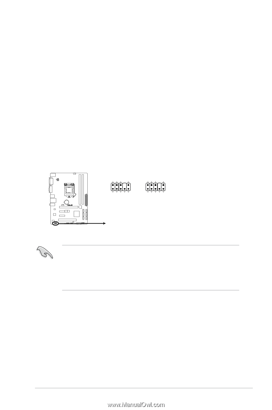
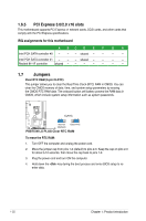
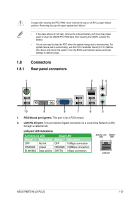
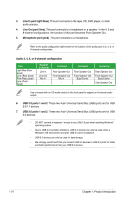
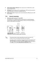
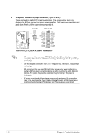
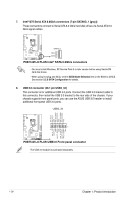
8. Video Graphics Adapter (VGA) port. This 15-pin port is for a VGA monitor or other VGA-compatible devices. 9. DVI-D port. This port is for any DVI-D compatible device. DVI-D can't be converted to output RGB Signal to CRT and isn't compatible with DVI-I. 10. USB 2.0 ports 3 and 4. These two 4-pin Universal Serial Bus (USB) ports are for USB 2.0/1.1 devices. 1.8.2 Internal connectors 1. Front panel audio connector (10-1 pin AAFP) This connector is for a chassis-mounted front panel audio I/O module that supports either HD Audio or legacy AC`97 audio standard. Connect one end of the front panel audio I/O module cable to this connector. AGND NC SENSE1_RETUR SENSE2_RETUR AGND NC NC NC AAFP PIN 1 PIN 1 MIC2 MICPWR Line out_R NC Line out_L PORT1 L PORT1 R PORT2 R SENSE_SEND PORT2 L P8B75-M LX PLUS HD-audio-compliant Legacy AC'97 pin definition compliant definition P8B75-M LX PLUS Front panel audio connector • We recommend that you connect a high-definition front panel audio module to this connector to avail of the motherboard's high-definition audio capability. • If you want to connect a high-definition front panel audio module to this connector, set the Front Panel Type item in the BIOS setup to [HD]. If you want to connect an AC'97 front panel audio module to this connector, set the item to [AC97]. By default, this connector is set to [HD]. See section 2.5.7 Onboard Devices Configuration for details. ASUS P8B75-M LX PLUS 1-25
-
 1
1 -
2
-
3
-
4
-
5
-
6
-
7
-
8
-
9
-
10
-
11
-
12
-
13
-
14
-
15
-
16
-
17
-
18
-
19
-
20
-
21
-
22
-
23
-
24
-
25
-
26
-
27
-
28
-
29
-
 30
30 -
 31
31 -
 32
32 -
 33
33 -
 34
34 -
 35
35 -
 36
36 -
 37
37 -
 38
38 -
 39
39 -
 40
40 -
41
-
42
-
43
-
44
-
45
-
46
-
47
-
48
-
49
-
50
-
51
-
52
-
53
-
54
-
55
-
56
-
57
-
58
-
59
-
60
-
61
-
62
-
63
-
64
-
65
-
66
-
67
-
68
-
69
-
70
-
71
-
72
-
73
-
74
-
75
-
76
-
77
-
78
-
79
-
80
 |
 |