Asus Pro WS WRX90E-SAGE SE IPMI EXPANSION CARD Users Manual English - Page 12
IPMI Expansion Card Overview, RTL8211F-CG 1G LAN connector, Onboard VGA header, VGA connector
 |
View all Asus Pro WS WRX90E-SAGE SE manuals
Add to My Manuals
Save this manual to your list of manuals |
Page 12 highlights
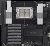
1.4 IPMI Expansion Card Overview RTL8211F-CG 1G LAN connector: Connects directly to the central server or to a router/hub using a LAN cable. Onboard VGA header: Connects to front VGA using an adapter cable. VGA connector: Connects to a display using a VGA cable. Fan headers 1-8: Connects to fans to view fan information and management. To use the CHA FAN sensor and control function, ensure the fans are connected to the Fan headers 1-8, and the 6-pin PSU connector is connected to a power supply. SPI header: Connects to IPMI TPM adapter with cable for burning BIOS. • Client device motherboard model needs to support this function. • To use the BIOS burning function, ensure the SPI header is connected to the IPMI TPM header on the motherboard. PANEL header: Connects to motherboard and chassis PANEL to control power/reset functions. To use the power on/off and reset function, ensure the PANEL header is connected to the motherboard and the chassis panel. T_SENSOR headers 1-3: Used for temperature measuring. To use the TR temperature sensor function, ensure the T_SENSOR headers 1-3 are connected to the motherboard. BMC header: Connects to motherboard BMC header for real-time sensor monitoring. To use the real-time sensor monitoring function (if supported), ensure the BMC header is connected to the BMC header on the motherboard. 1-4 Chapter 1: Product Introduction
-
 1
1 -
2
-
3
-
4
-
5
-
6
-
 7
7 -
 8
8 -
 9
9 -
 10
10 -
 11
11 -
 12
12 -
 13
13 -
 14
14 -
 15
15 -
 16
16 -
 17
17 -
18
-
19
-
20
-
21
-
22
-
23
-
24
-
25
-
26
-
27
-
28
-
29
-
30
-
31
-
32
-
33
-
34
-
35
-
36
-
37
-
38
-
39
-
40
-
41
-
42
-
43
-
44
-
45
-
46
-
47
-
48
-
49
-
50
-
51
-
52
-
53
-
54
-
55
-
56
-
57
-
58
-
59
-
60
-
61
-
62
-
63
-
64
-
65
-
66
-
67
-
68
-
69
-
70
-
71
-
72
-
73
-
74
-
75
-
76
-
77
-
78
-
79
-
80
-
81
-
82
-
83
-
84
-
85
-
86
-
87
-
88
-
89
-
90
-
91
-
92
-
93
-
94
-
95
-
96
-
97
-
98
-
99
-
100
-
101
-
102
-
103
-
104
-
105
-
106
-
107
-
108
-
109
-
110
-
111
-
112
-
113
-
114
-
115
-
116
-
117
-
118
-
119
-
120
-
121
-
122
 |
 |
