Asus Terminator Tualatin 786 MANUAL TERMINATOR TUALATIN English V1.0
Asus Terminator Tualatin Manual
 |
View all Asus Terminator Tualatin manuals
Add to My Manuals
Save this manual to your list of manuals |
Asus Terminator Tualatin manual content summary:
- Asus Terminator Tualatin | 786 MANUAL TERMINATOR TUALATIN English V1.0 - Page 1
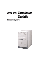
® Terminator Tualatin Barebone System User's Guide - Asus Terminator Tualatin | 786 MANUAL TERMINATOR TUALATIN English V1.0 - Page 2
A COMMITMENT BY ASUS. ASUS ASSUMES NO RESPONSIBILITY OR LIABILITY FOR ANY ERRORS OR INACCURACIES THAT MAY APPEAR IN THIS MANUAL, INCLUDING THE PRODUCTS AND SOFTWARE DESCRIBED IN IT. Copyright © 2001 ASUSTeK COMPUTER INC. All Rights Reserved. Product Name: Terminator Barebone System Manual Revision - Asus Terminator Tualatin | 786 MANUAL TERMINATOR TUALATIN English V1.0 - Page 3
Center, Building 2 Newark, CA 94560, USA +1-510-608-4555 [email protected] Technical Support Fax: +1-510-608-4555 BBS: +1-510-739-3774 Email: [email protected] WWW: www.asus.com FTP: ftp.asus.com.tw/pub/ASUS ASUS COMPUTER GmbH (Europe) Marketing Address: Fax: Email: Harkortstr. 25, 40880 - Asus Terminator Tualatin | 786 MANUAL TERMINATOR TUALATIN English V1.0 - Page 4
. This equipment generates, uses and can radiate radio frequency energy and, if not installed and used in accordance with manufacturer's instructions, may cause harmful interference to radio communications. However, there is no guarantee that interference will not occur in a particular installation - Asus Terminator Tualatin | 786 MANUAL TERMINATOR TUALATIN English V1.0 - Page 5
: About This Guide 9 Audience 10 Contents Description 10 Chapter 1: System Introduction 11 1.1 Front Panel Features 12 1.2 Rear Panel Features 13 Chapter 2: Basic Installation 15 2.1 Remove the Cover 16 2.2 Detach the Drive Frame 17 2.3 Install a CPU 19 2.4 Install System Memory 21 - Asus Terminator Tualatin | 786 MANUAL TERMINATOR TUALATIN English V1.0 - Page 6
3.7 Central Processing Unit (CPU 46 3.8 Expansion Cards 47 3.9 Connectors 49 Chapter 4: Starting Up 61 4.1 Powering Up the First Time 62 4.2 Install the Operating System 64 4.3 ASUS PC Probe 67 Chapter 5: BIOS Information 73 5.1 Managing and Updating Your BIOS 74 5.2 BIOS Setup Program 78 - Asus Terminator Tualatin | 786 MANUAL TERMINATOR TUALATIN English V1.0 - Page 7
Chassis 2) Motherboard 3) Switching Power Supply 4) 1.44MB Floppy Disk Drive 5) CD-ROM Drive (optional) 6) 56K PCI Modem Card (optional) 7) Support CD with Drivers and Utilities 8) User's Guide NOTE If you are assembling the system by yourself, make sure to prepare all the components before starting - Asus Terminator Tualatin | 786 MANUAL TERMINATOR TUALATIN English V1.0 - Page 8
NOTES 8 - Asus Terminator Tualatin | 786 MANUAL TERMINATOR TUALATIN English V1.0 - Page 9
Introduction You are reading the ASUS Terminator Barebone System Installation Guide. This guide provides general information and installation instructions about the Terminator Barebone System. "About This Guide" contains an introduction on the contents of this document that include target audience - Asus Terminator Tualatin | 786 MANUAL TERMINATOR TUALATIN English V1.0 - Page 10
tells how to install components into the barebone system through illustrated step-by-step instructions. 4. Chapter 3: Motherboard Information This chapter gives information about the TUSC motherboard that comes with the ASUS Terminator Barebone System.This chapter includes the motherboard layout - Asus Terminator Tualatin | 786 MANUAL TERMINATOR TUALATIN English V1.0 - Page 11
System Introduction Chapter 1 This chapter gives a general description of the ASUS Terminator barebone system. It includes introduction on the front and rear panel features, and the internal features. ASUS Terminator Barebone System 11 - Asus Terminator Tualatin | 786 MANUAL TERMINATOR TUALATIN English V1.0 - Page 12
1.1 Front Panel Features The ASUS Terminator barebone system is composed of the ASUS TUSC motherboard, a power supply, and a floppy disk drive in the ASUS TriOptix form factor chassis. The following figures show the front panel features. NOTE The CD-ROM drive and modem card are optional items and - Asus Terminator Tualatin | 786 MANUAL TERMINATOR TUALATIN English V1.0 - Page 13
1.2 Rear Panel Features The rear panel of the ASUS Terminator barebone system includes the standard PC99 I/O connectors for external devices, power supply socket, and optional ! Setting the switch to 115V in a 230V environment will seriously damage the system. ASUS Terminator Barebone System 13 - Asus Terminator Tualatin | 786 MANUAL TERMINATOR TUALATIN English V1.0 - Page 14
1.3 Internal Features The figure below shows the internal view of the system when you remove the cover and flip out the drive frame. You will see here the standard components that come already installed in the system and the places where you can install the other required components to get the - Asus Terminator Tualatin | 786 MANUAL TERMINATOR TUALATIN English V1.0 - Page 15
Chapter 2 This chapter tells how to install components into the barebone system through illustrated step-by-step instructions. Basic Installation ASUS Terminator Barebone System 15 - Asus Terminator Tualatin | 786 MANUAL TERMINATOR TUALATIN English V1.0 - Page 16
the rest of your fingers pulling forward from both sides, push on the CD-ROM area with your thumbs until the cover tilts forward. 3. While supporting the front panel with one hand, place your other hand on the top rear edge of the cover and carefully lift the cover from the - Asus Terminator Tualatin | 786 MANUAL TERMINATOR TUALATIN English V1.0 - Page 17
. Power Socket Module Module screw WARNING! Do not plug in the main power cable into the power socket until you have completed the system installation. ASUS Terminator Barebone System 17 - Asus Terminator Tualatin | 786 MANUAL TERMINATOR TUALATIN English V1.0 - Page 18
2.2 Detach the Drive Frame 3. Place your thumb on the right edge of the power socket module, and slide it to the right until it is completely detached the module from the rear panel. 4. Unlatch the drive frame by pulling it outward. Drive Frame Swivel Edge NOTE The drive frame has a swivel (hinge- - Asus Terminator Tualatin | 786 MANUAL TERMINATOR TUALATIN English V1.0 - Page 19
Pentium III/Celeron processor. Follow these steps to install a CPU. 1. Locate the CPU socket on the motherboard. CPU Fan Connector (CPU_FAN) CPU Socket 370 2. Unlock the socket by pressing the lever sideways then lifting it up to a 90°-100° angle. Socket Pin 1 ASUS Terminator Barebone System 19 - Asus Terminator Tualatin | 786 MANUAL TERMINATOR TUALATIN English V1.0 - Page 20
CPU_FAN connector on the motherboard. Refer to the picture in step 1. CPU Fan Cable WARNING! The CPU fits only in one orientation. DO NOT force the CPU into the socket to prevent bending the pins and damaging the CPU. If the CPU does not fit completely, check its orientation or check for bent - Asus Terminator Tualatin | 786 MANUAL TERMINATOR TUALATIN English V1.0 - Page 21
includes two 168-pin Dual Inline Memory Module (DIMM) sockets. The sockets support up to 1GB system memory using PC133-compliant Synchronous Dynamic Random Access Memory (SDRAM) DIMMs. Follow these steps in place and the DIMM is properly seated. Installed DIMM ASUS Terminator Barebone System 21 - Asus Terminator Tualatin | 786 MANUAL TERMINATOR TUALATIN English V1.0 - Page 22
2.5 Install a Hard Disk Drive The chassis has one 3.5-inch hard disk drive (HDD) bay right under the 5.25-inch bay. The following figures show the internal and external views of the HDD bay location. Internal View External View 5.25-inch Drive Bay 3.5-inch HDD Drive Bay Follow these steps to - Asus Terminator Tualatin | 786 MANUAL TERMINATOR TUALATIN English V1.0 - Page 23
) 7. Connect the other end of the IDE ribbon cable to the primary IDE connector (blue connector labeled IDE1) on the motherboard. Primary IDE Connector (IDE1) ASUS Terminator Barebone System 23 - Asus Terminator Tualatin | 786 MANUAL TERMINATOR TUALATIN English V1.0 - Page 24
2.6 Install a CD-ROM Drive A CD-ROM drive is an optional item in this barebone system. Refer to the instructions in this section if you acquired a model without a CD-ROM. Follow these steps to install a CD-ROM drive. 1. Place the chassis upright. 2. Insert the CD- - Asus Terminator Tualatin | 786 MANUAL TERMINATOR TUALATIN English V1.0 - Page 25
the other end of the audio cable to the black 4-pin connector labeled CD on the motherboard. CD-ROM Connector (CD) Secondary IDE Connector (IDE2) ASUS Terminator Barebone System 25 - Asus Terminator Tualatin | 786 MANUAL TERMINATOR TUALATIN English V1.0 - Page 26
2.7 Install a Modem Riser Card The motherboard includes an AMR slot that supports a modem riser card. The modem riser card is an optional item in the Terminator barebone system. Refer to the instructions in this section if you acquired a model without a modem riser card. The figure on the right - Asus Terminator Tualatin | 786 MANUAL TERMINATOR TUALATIN English V1.0 - Page 27
slots (one shared with AMR slot). If you wish to install a PCI card, refer to the instructions in this section. The figure on the right shows a sample PCI network card that you can install on screw. Slot Opening for PCI1 PCI Slot 1 (PCI1) PCI Slot 2 (PCI2) ASUS Terminator Barebone System 27 - Asus Terminator Tualatin | 786 MANUAL TERMINATOR TUALATIN English V1.0 - Page 28
re-connect these cables before you replace the chassis cover. 2.9.1 Front Panel Cables The figure below shows the front panel cables with corresponding instructions on where to connect them. Power Switch Power LED HDD LED Headphone / Mic USB Connector (USB2P) 1. Connect the power switch and power - Asus Terminator Tualatin | 786 MANUAL TERMINATOR TUALATIN English V1.0 - Page 29
® LOUT LO2 MIC MIC2 Connect to USB1 Connector on the Motherboard Connect to FLOUT Lead on the Motherboard Connect to MIC2 Lead on the Motherboard ASUS Terminator Barebone System 29 - Asus Terminator Tualatin | 786 MANUAL TERMINATOR TUALATIN English V1.0 - Page 30
2.10 Replace the Cover After you have installed all the internal components and you have connected all the necessary cables, you are now ready to put the system back together. Follow these steps to re-assemble the system. 1. With the chassis lying on its side, hook the swivel edge of the drive - Asus Terminator Tualatin | 786 MANUAL TERMINATOR TUALATIN English V1.0 - Page 31
Firmly push the cover to ensure that it is fully engaged to the chassis. 7. Lock the cover with the captive thumbscrew on the rear panel. ASUS Terminator Barebone System 31 - Asus Terminator Tualatin | 786 MANUAL TERMINATOR TUALATIN English V1.0 - Page 32
2.11 Connect External Devices The figure below shows the specific connectors and devices that you can connect to the rear panel ports. Serial PS/2 KB VGA Line Out Line In Mic RJ-45 Game/MIDI PS/2 Mouse Parallel AC USB 32 Chapter 2: Basic Installation - Asus Terminator Tualatin | 786 MANUAL TERMINATOR TUALATIN English V1.0 - Page 33
+5V +12V +3.3V Maximum Voltage 6.5V 15.6V 4.3V NOTE The power supply will shut down and latch off for shorting +5V, +12V, -12V, -5V, or +3.3V. By shorting +5Vsb, the power supply can latch down or automatically recover when the fault condition is removed. ASUS Terminator Barebone System 33 - Asus Terminator Tualatin | 786 MANUAL TERMINATOR TUALATIN English V1.0 - Page 34
NOTES 34 Chapter 2: Basic Installation - Asus Terminator Tualatin | 786 MANUAL TERMINATOR TUALATIN English V1.0 - Page 35
Chapter 3 This chapter gives detailed technical information about the different features of the TUSC motherboard - the heart of the Terminator Barebone System . M/B Information ASUS Terminator Barebone System 35 - Asus Terminator Tualatin | 786 MANUAL TERMINATOR TUALATIN English V1.0 - Page 36
3.1 Specifications The ASUS TUSC motherboard targets users who require a noncomplicated yet flexible system. This motherboard includes the basic features sufficient for an entry-level system while employing the latest in technology. • Latest Processor Support: PIII® Tualatin™ 133/100MHz FSB FC- - Asus Terminator Tualatin | 786 MANUAL TERMINATOR TUALATIN English V1.0 - Page 37
Super I/O controller also supports a floppy disk drive. -RAM (STR) feature that provides maximum power savings while leaving your computer CPU and system voltages, temperatures, and fan status through the onboard hardware ASUS (Mozart-1) ASIC and the bundled ASUS PC Probe. ASUS Terminator Barebone - Asus Terminator Tualatin | 786 MANUAL TERMINATOR TUALATIN English V1.0 - Page 38
Processor ....... 5 Chipsets SiS630ET 3C Integration Single Chip 7 Super I/O Controller 4 2Mbit Programmable Flash EEPROM 3 Main Memory Maximum 1GB support 2 DIMM Sockets 8 PC133 SDRAM support Expansion Slot 2 Riser PCI Slots 14 1 AMR Slot 12 System I/O IOC_MB Connector 1 1 Floppy Disk - Asus Terminator Tualatin | 786 MANUAL TERMINATOR TUALATIN English V1.0 - Page 39
3.2.1 Component Locations 12 3 45 6 7 89 23 22 21 20 19 18 17 16 15 14 13 12 11 10 ASUS Terminator Barebone System 39 - Asus Terminator Tualatin | 786 MANUAL TERMINATOR TUALATIN English V1.0 - Page 40
a serial port (COM1) and Game/MIDI port. GAME ® CGAEX IOC_DC COM1 18.9cm (7.44in) TUSC FS1 FS2 FS0 PS/2 T: Mouse B: Keyboard VGA 22.9cm (9.01in) IOC_MB Flash BIOS Super I/O 3V Lithium Cell CMOS Power 1 1 USB1 CLRTC ASUS Mozart PANEL IDELED 40 Chapter 3: Motherboard Information - Asus Terminator Tualatin | 786 MANUAL TERMINATOR TUALATIN English V1.0 - Page 41
must complete the following steps: 1. Check motherboard settings 2. Install memory modules 3. Install the Central Processing Unit (CPU) 4. Install an expansion card 5. Connect ribbon cables, panel wires the system is in suspend or soft-off mode, not powered OFF. ASUS Terminator Barebone System 41 - Asus Terminator Tualatin | 786 MANUAL TERMINATOR TUALATIN English V1.0 - Page 42
clear the Real Time Clock (RTC) RAM in CMOS. You can clear the CMOS memory of date, time, and system setup parameters by erasing the CMOS RTC RAM data process and enter BIOS setup to re-enter data. TUSC ® TUSC Clear RTC RAM CR2032 3V Lithium Cell CMOS Power CLRTC Short solder points to - Asus Terminator Tualatin | 786 MANUAL TERMINATOR TUALATIN English V1.0 - Page 43
boot up. FS2 FS1 FS0 FS2 FS1 FS0 FS2 FS1 FS0 FS2 FS1 FS0 TUSC 1 1 1 1 ® CPU 66.8MHz 66.6MHz 100.0MHz 100.0MHz SDRAM 66.8MHz 100.0MHz 100.0MHz parameter in BIOS when you use a primary AMR. TUSC ® TUSC PDN Setting PDN 12 Normal 23 AUDIO DIS ASUS Terminator Barebone System 43 - Asus Terminator Tualatin | 786 MANUAL TERMINATOR TUALATIN English V1.0 - Page 44
DIMMs that have more than 18 chips are not supported on this motherboard. • For the system CPU bus to operate 100MHz/133MHz, use only PC100-/PC133-compliant DIMMs. • ASUS motherboards support Serial Presence Detect (SPD) DIMMs. This is the memory of choice for best performance vs. stability. • SDRAM - Asus Terminator Tualatin | 786 MANUAL TERMINATOR TUALATIN English V1.0 - Page 45
the power supply when adding or removing memory modules or other system components. Failure type, check the notches on the DIMMs (see the figure below). TUSC The notches on the DIMM shifts between left, center, or right to supports four clock signals per DIMM. ASUS Terminator Barebone System 45 - Asus Terminator Tualatin | 786 MANUAL TERMINATOR TUALATIN English V1.0 - Page 46
a ZIF Socket to support CPUs as listed on section 3.1.1 Specifications. The following illustration shows the CPU socket location on the motherboard and the correct CPU orientation. Pentium III Celeron (Coppermine) FC-PGA TUSC ® Gold Arrow Pentium III (Tualatin) FC-PGA2 TUSC Socket 370 Gold - Asus Terminator Tualatin | 786 MANUAL TERMINATOR TUALATIN English V1.0 - Page 47
IRQs free for expansion cards. IMPORTANT: If using PCI cards on shared slots, make sure that the drivers support "Share IRQ" or that the cards do not need IRQ assignments. Conflicts arise between the two PCI IRQs are usually available for ISA or PCI devices. ASUS Terminator Barebone System 47 - Asus Terminator Tualatin | 786 MANUAL TERMINATOR TUALATIN English V1.0 - Page 48
Audio Modem Riser (AMR) Slot The AMR slot support a specially designed audio and/or modem card called shares the same expansion slot with PCI Slot 6. Because of space limitation, the AMR slot can support only specially designed AMR cards. The components of a standard AMR card and its bracket face - Asus Terminator Tualatin | 786 MANUAL TERMINATOR TUALATIN English V1.0 - Page 49
not allow standard AT size (large DIN) keyboard plugs. You may use a DIN to mini DIN adapter on standard AT keyboards. PS/2 Keyboard (6-pin female) ASUS Terminator Barebone System 49 - Asus Terminator Tualatin | 786 MANUAL TERMINATOR TUALATIN English V1.0 - Page 50
3. VGA Connector (Blue 15-pin VGA) This connector is for a VGA monitor and other VGA-compatible devices. VGA Monitor (15-pin female) 4. Parallel Port Connector (Burgundy 25-pin PRINTER) You can enable the parallel port and choose the IRQ through Onboard Parallel Port (see 5.4.2 I/O Device - Asus Terminator Tualatin | 786 MANUAL TERMINATOR TUALATIN English V1.0 - Page 51
Serial Bus (USB) 8. Game/MIDI Connector (Gold 15-pin GAME_AUDIO) This connector, located on the CGAEX extension module, supports a joystick or a game pad for playing games, and MIDI devices for playing or editing audio files. Joystick/Midi (15-pin female) ASUS Terminator Barebone System 51 - Asus Terminator Tualatin | 786 MANUAL TERMINATOR TUALATIN English V1.0 - Page 52
9. Serial Port Connector (Teal/Turquoise 9-pin COM1) on CGAEX One serial port, located on the CGAEX extension module, is available for a mouse or other serial devices. COM1 Serial Port (9-Pin male) 10. USB/Audio Board (UAEX module): USB (Ports 2&3) and Audio Port Connectors (LOUT & MIC) Located on - Asus Terminator Tualatin | 786 MANUAL TERMINATOR TUALATIN English V1.0 - Page 53
the hard disk documentation for the jumper settings. BIOS supports specific device bootup (see 5.6 Boot Menu). If TUSC Secondary IDE Connector Primary IDE Connector ® NOTE: Orient the red markings (usually zigzag) on the IDE ribbon cable to PIN 1. TUSC IDE Connectors PIN 1 ASUS Terminator Barebone - Asus Terminator Tualatin | 786 MANUAL TERMINATOR TUALATIN English V1.0 - Page 54
® TUSC USB Ports USB Power USBP3- USBP3+ GND USB Power USBP2- USBP2+ GND NC 1 5 6 10 3. Infrared Module Connector (5-pin IR) This connector supports an optional wireless transmitting and receiving infrared module. This module mounts to a small opening on a system chassis that supports this - Asus Terminator Tualatin | 786 MANUAL TERMINATOR TUALATIN English V1.0 - Page 55
4. CPU and Chassis Fan Connectors The two 3-pin fan connectors (CPU_FAN, CHA_FAN) support cooling fans of 350mA (4.2 Watts) the IDE LED to light up. TUSC ® TIP: If the case-mounted LED does not light, try reversing the 2-pin plug. IDELED TUSC IDE Activity LED ASUS Terminator Barebone System 55 - Asus Terminator Tualatin | 786 MANUAL TERMINATOR TUALATIN English V1.0 - Page 56
(+5VSB). You may experience difficulty in turning the system ON if the power supply cannot support the load. For Wake-On-LAN support, the ATX power supply must supply at least 720mA +5VSB. TUSC ® TUSC ATX Power Connector +3.3Volts -12.0Volts Ground Power Supply On Ground Ground Ground -5.0 Volts - Asus Terminator Tualatin | 786 MANUAL TERMINATOR TUALATIN English V1.0 - Page 57
on the floppy ribbon cable to PIN 1. TUSC Floppy Disk Drive Connector 9. IOC_MB Connector (22-pin) This connects the motherboard to the CGAEX extension module which contains the COM1 and GAME ports. TUSC COM1 GAME ® ® CGAEX IOC_DC TUSC IOC_MB Connector ASUS Terminator Barebone System 57 - Asus Terminator Tualatin | 786 MANUAL TERMINATOR TUALATIN English V1.0 - Page 58
TUSC 10. Internal Microphone (2-pin) and FLOUT (3-pin) Connectors This connects to the LO2/MIC2 connector located on the front the front audio jack. Head set Left channel ® Head set Right channel GND FLOUT 1 MIC2 1 MIC PWR MIC Signal TUSC Microphone Header 58 Chapter 3: Motherboard Information - Asus Terminator Tualatin | 786 MANUAL TERMINATOR TUALATIN English V1.0 - Page 59
SMI Lead PLED Power LED +5 V TB_LED +5 V Message LED TUSC System Panel Connectors * Requires an ATX power supply. 11. System OS and driver support. 14. System Management Interrupt Connector (2-pin SMI) This 2-pin connector allows you to manually place the ASUS Terminator Barebone System 59 - Asus Terminator Tualatin | 786 MANUAL TERMINATOR TUALATIN English V1.0 - Page 60
NOTES 60 Chapter 3: Motherboard Information - Asus Terminator Tualatin | 786 MANUAL TERMINATOR TUALATIN English V1.0 - Page 61
Chapter 4 This chapter describes the power-up sequence and gives information on the BIOS beep codes. The contents of the support CD that comes with the Terminator Barebone System package are also enumerated. Starting Up ASUS Terminator Barebone System 61 - Asus Terminator Tualatin | 786 MANUAL TERMINATOR TUALATIN English V1.0 - Page 62
Long beeps in an endless loopNo DRAM installed or detected One long beep followed by Video card not found or video card three short beeps memory bad High frequency beeps when CPU overheated system is working System running at a lower frequency 62 Chapter 4: Starting Up - Asus Terminator Tualatin | 786 MANUAL TERMINATOR TUALATIN English V1.0 - Page 63
7. At power on, hold down to enter BIOS Setup. Follow the instructions in 5.1 Managing and Updating Your BIOS. * Powering Off the Computer: You must first exit now safely turn off your computer" does not appear when shutting down with ATX power supplies. ASUS Terminator Barebone System 63 - Asus Terminator Tualatin | 786 MANUAL TERMINATOR TUALATIN English V1.0 - Page 64
Wizard to install all the necessary device drivers. When prompted to restart, select No, then follow the normal setup procedures on the screen. 4.2.2 TUSC Motherboard Support CD To begin using the support CD, insert it into the CD-ROM drive. The support installation menu should appear. If the menu - Asus Terminator Tualatin | 786 MANUAL TERMINATOR TUALATIN English V1.0 - Page 65
the ASUS Update program. This program allows you download the latest version of Flash BIOS from the ASUS website. Before using ASUS Update, you should install a network card and a TCP/IP network driver. • Microsoft DirectX 8.0a Driver: Installs the Microsoft Direct Driver. ASUS Terminator Barebone - Asus Terminator Tualatin | 786 MANUAL TERMINATOR TUALATIN English V1.0 - Page 66
V5.0: Installs the Adobe Acrobat Reader software necessary to view user's manuals in PDF format. NOTE: To see the following items, click on CPU. • Browse Support CD: Allows you to view the contents of the support CD. • ReadMe: Allows you to view a list of the files included in the support CD and ASUS - Asus Terminator Tualatin | 786 MANUAL TERMINATOR TUALATIN English V1.0 - Page 67
ASUS PC Probe, click the Windows Start button, point to Programs, and then ASUS Utility, and then click Probe Vx.xx. The PC Probe icon appears on the taskbar system tray indicating that ASUS PC Probe is running. Clicking the icon allows you to see the status of your PC. ASUS Terminator Barebone - Asus Terminator Tualatin | 786 MANUAL TERMINATOR TUALATIN English V1.0 - Page 68
4.3.2 Using ASUS PC Probe Monitoring Monitor Summary Shows a summary of the items being monitored. Temperature Monitor Shows the PC temperature (for supported processors only). Temperature Warning threshold adjustment (Move the slider up to increase the threshold level or down to decrease the - Asus Terminator Tualatin | 786 MANUAL TERMINATOR TUALATIN English V1.0 - Page 69
Smart Fan Control. Smart Fan Control adjusts the fan speed automatically based on the current CPU temperature and predefined threshold. Hard Drives Shows the used and free space of the PC's hard disk drives and the file allocation table or file system used. ASUS Terminator Barebone System 69 - Asus Terminator Tualatin | 786 MANUAL TERMINATOR TUALATIN English V1.0 - Page 70
devices present in your PC. DMI Explorer Shows information pertinent to the PC, such as CPU type, CPU speed, and internal/external frequencies, and memory size. Utility Lets you run programs outside of the ASUS Probe modules. To run a program, click Execute Program. NOTE: This feature is currently - Asus Terminator Tualatin | 786 MANUAL TERMINATOR TUALATIN English V1.0 - Page 71
icon brings up a menu to open or exit ASUS PC Probe and pause or resume all system monitoring. When the ASUS PC Probe senses a problem with your PC, portions of the ASUS PC Probe icon changes to red, the PC speaker beeps, and the ASUS PC Probe monitor appears. ASUS Terminator Barebone System 71 - Asus Terminator Tualatin | 786 MANUAL TERMINATOR TUALATIN English V1.0 - Page 72
NOTES 72 Chapter 4: Starting Up - Asus Terminator Tualatin | 786 MANUAL TERMINATOR TUALATIN English V1.0 - Page 73
Chapter 5 This chapter gives details on how to change system settings using the BIOS setup menus. BIOS Information ASUS Terminator Barebone System 73 - Asus Terminator Tualatin | 786 MANUAL TERMINATOR TUALATIN English V1.0 - Page 74
work in the DOS prompt within Windows and does not work with certain memory drivers that may be loaded when you boot from the hard drive. It is the word "unknown" appears after Flash Memory:, the memory chip is either not programmable or is not supported by the ACPI BIOS and therefore, cannot be - Asus Terminator Tualatin | 786 MANUAL TERMINATOR TUALATIN English V1.0 - Page 75
5. Select 1. Save Current BIOS to File from the Main menu and press . The Save Current BIOS To File screen appears. 6. Type a filename and the path, for example, A:\XXX-XX.XXX and then press . ASUS Terminator Barebone System 75 - Asus Terminator Tualatin | 786 MANUAL TERMINATOR TUALATIN English V1.0 - Page 76
your motherboard and you know that the new BIOS revision will solve your problems. Careless updating can result in your motherboard having more problems! 1. Download an updated ASUS BIOS file from the Internet (WWW or FTP) (see ASUS CONTACT INFORMATION on page 3 for details) and save to the disk you - Asus Terminator Tualatin | 786 MANUAL TERMINATOR TUALATIN English V1.0 - Page 77
, and if the problem still persists, update the original BIOS file you saved to the disk above. If the Flash Memory Writer utility was not able to successfully update a complete BIOS file, the system may not boot. If this happens, the system will need servicing. ASUS Terminator Barebone System 77 - Asus Terminator Tualatin | 786 MANUAL TERMINATOR TUALATIN English V1.0 - Page 78
5.2 BIOS Setup Program This motherboard supports a programmable EEPROM that can be updated using the provided utility as described in 5.1 Managing and Updating Your BIOS. The utility is used if you are - Asus Terminator Tualatin | 786 MANUAL TERMINATOR TUALATIN English V1.0 - Page 79
or Moves the cursor to the last field Resets the current screen to its Setup Defaults Saves changes and exits Setup ASUS Terminator Barebone System 79 - Asus Terminator Tualatin | 786 MANUAL TERMINATOR TUALATIN English V1.0 - Page 80
General Help In addition to the Item Specific Help window, the BIOS setup program also provides a General Help screen. This screen can be called up from any menu by simply pressing or the + combination. The General Help screen lists the legend keys with their corresponding alternates - Asus Terminator Tualatin | 786 MANUAL TERMINATOR TUALATIN English V1.0 - Page 81
] [1.44M, 3.5 in.] Floppy 3 Mode Support [Disabled] This is required to support older Japanese floppy drives. The Floppy 3 Mode feature allows reading and writing of 1.2MB (as opposed to 1.44MB) on a 3.5-inch diskette. Configuration options: [Disabled] [Enabled] ASUS Terminator Barebone System 81 - Asus Terminator Tualatin | 786 MANUAL TERMINATOR TUALATIN English V1.0 - Page 82
, your hard disk drive may be too old or too new. You can try updating your BIOS or enter the IDE hard disk drive parameters manually. NOTE: After the IDE hard disk drive information has been entered into BIOS, new IDE hard disk drives must be partitioned (such as with FDISK - Asus Terminator Tualatin | 786 MANUAL TERMINATOR TUALATIN English V1.0 - Page 83
an older previous system, incorrect parameters may be detected. You will need to enter the correct parameters manually or use low-level format if you do not need the data stored on the hard disk. HDD] and the Translation Method field must be set to [Manual]. ASUS Terminator Barebone System 83 - Asus Terminator Tualatin | 786 MANUAL TERMINATOR TUALATIN English V1.0 - Page 84
BIOS from the drive information you entered. Multi-Sector Transfers [Maximum] This option automatically sets the number of sectors per block to the highest number supported by the drive. This field can also be configured manually. Note that when this field is automatically configured, the set value - Asus Terminator Tualatin | 786 MANUAL TERMINATOR TUALATIN English V1.0 - Page 85
/Sec] Keyboard Auto-Repeat Delay [1/4 Sec] This field sets the time interval for displaying the first and second characters. Configuration options: [1/4 Sec] [1/2 Sec] [3/4 Sec] [1 Sec] ASUS Terminator Barebone System 85 - Asus Terminator Tualatin | 786 MANUAL TERMINATOR TUALATIN English V1.0 - Page 86
Power TUSC Clear RTC RAM CLRTC Short solder points to Clear CMOS Halt On [All but Keyboard] This field determines which types of errors will cause the system to halt. Configuration options: [All Errors] [No Error] [All but Keyboard] [All but Disk] [All but Disk/Keyboard] Installed Memory [XXX - Asus Terminator Tualatin | 786 MANUAL TERMINATOR TUALATIN English V1.0 - Page 87
] to turn on or off the CPU's Level 1 and Level 2 built-in cache. Configuration options: [Disabled] [Enabled] CPU Level 2 Cache ECC Check [Disabled] This function controls the ECC capability in the CPU level 2 cache. Configuration options: [Disabled] [Enabled] ASUS Terminator Barebone System 87 - Asus Terminator Tualatin | 786 MANUAL TERMINATOR TUALATIN English V1.0 - Page 88
not. Configuration options: [Enabled] [Auto] USB Legacy Support [Auto] This motherboard supports Universal Serial Bus (USB) devices. The default of [ not. Configuration options: [Disabled] [Enabled] [Auto] OS/2 Onboard Memory > 64M [Disabled] When using OS/2 operating systems with installed DRAM of - Asus Terminator Tualatin | 786 MANUAL TERMINATOR TUALATIN English V1.0 - Page 89
SPD (Serial Presence Detect) device. The EEPROM on the memory module stores critical parameter information about the module, such as memory type, size, speed, voltage interface, and module banks. only when you set the SDRAM Configuration to [User Defined]. ASUS Terminator Barebone System 89 - Asus Terminator Tualatin | 786 MANUAL TERMINATOR TUALATIN English V1.0 - Page 90
[Enabled] CPU to VGA Memory Post Write [Enabled] Configuration options: [Enabled] [Disabled] Video Memory Cache Mode [ support this feature, otherwise the system may not boot. Configuration options: [UC] [USWC] Graphics Aperture Size [64MB] This feature allows you to select the size of mapped memory - Asus Terminator Tualatin | 786 MANUAL TERMINATOR TUALATIN English V1.0 - Page 91
TV] [Hi-TV only] NOTE The TUSC motherboard does not support the LCD & TV Out function. The default setting should not be changed. PCI 2.1 Support [Enabled] This parameter allows you to ] Onboard LAN Boot ROM [Enabled] Configuration options: [Enabled] [Disabled] ASUS Terminator Barebone System 91 - Asus Terminator Tualatin | 786 MANUAL TERMINATOR TUALATIN English V1.0 - Page 92
5.4.2 I/O Device Configuration Onboard AC97 Modem Controller [Enabled] Onboard AC97 Audio Controller [Enabled] [Auto] allows the motherboard's BIOS to detect whether you are using any modem/audio device. If a modem/audio device is detected, the onboard modem/audio controller will be enabled; if no - Asus Terminator Tualatin | 786 MANUAL TERMINATOR TUALATIN English V1.0 - Page 93
this field activates the onboard standard infrared feature and sets the second serial UART to support the infrared module connector on the motherboard. If your system already has a second serial [ECP+EPP] in Parallel Port Mode above. Configuration options: [1] [3] ASUS Terminator Barebone System 93 - Asus Terminator Tualatin | 786 MANUAL TERMINATOR TUALATIN English V1.0 - Page 94
VGA cards, such as graphics accelerators or MPEG video cards, may not show colors properly. The setting [Enabled] should correct this problem. Otherwise, leave this on the default setting of [Disabled]. Configuration options: [Disabled] [Enabled] PCI Latency Timer [32] Leave on default setting - Asus Terminator Tualatin | 786 MANUAL TERMINATOR TUALATIN English V1.0 - Page 95
IRQ for each field is being used by a specified device. The default value indicates that the displayed IRQ is not used. Configuration options: [No] [Yes] ASUS Terminator Barebone System 95 - Asus Terminator Tualatin | 786 MANUAL TERMINATOR TUALATIN English V1.0 - Page 96
expansion cards with ROMs on them, you will need to know which addresses the ROMs use to shadow them specifically. Shadowing a ROM reduces the memory available between 640K and 1024K by the amount used for this purpose. Configuration options: [Disabled] [Enabled] 96 Chapter 5: BIOS Information - Asus Terminator Tualatin | 786 MANUAL TERMINATOR TUALATIN English V1.0 - Page 97
its greatest amount. The Suspend Mode field will then be set to predefined value that ensures maximum power savings. This field acts as the master control for the power management modes. [Max Saving options: [User Define] [Disabled] [Min Saving] [Max Saving] ASUS Terminator Barebone System 97 - Asus Terminator Tualatin | 786 MANUAL TERMINATOR TUALATIN English V1.0 - Page 98
field defines the video off features. The DPMS (Display Power Management System) feature allows the BIOS to control the video display card if it supports the DPMS feature. [Blank Screen] only blanks the screen (use this for monitors without power management or "green" features. If set up in your - Asus Terminator Tualatin | 786 MANUAL TERMINATOR TUALATIN English V1.0 - Page 99
[Enabled] reboots your system. [Previous State] sets your system back to the state it is before the power interruption. Configuration options: [Disabled] [Enabled] [Previous State] ASUS Terminator Barebone System 99 - Asus Terminator Tualatin | 786 MANUAL TERMINATOR TUALATIN English V1.0 - Page 100
PWR Up On External Modem Act [Disabled] This allows either settings of [Enabled] or [Disabled] for powering up the computer when the external modem receives a call while the computer is in Soft-off mode. NOTE: The computer cannot receive or transmit data until the computer and applications are fully - Asus Terminator Tualatin | 786 MANUAL TERMINATOR TUALATIN English V1.0 - Page 101
the Power Supply and CPU temperatures. Chassis Fan Speed [N/A] CPU Fan Speed [xxxxRPM] / Chassis Fan Speed [xxxxRPM] The onboard hardware monitor is able to detect the CPU fan speed and the chassis be prompted to "Press F1 to continue, DEL to enter SETUP". ASUS Terminator Barebone System 101 - Asus Terminator Tualatin | 786 MANUAL TERMINATOR TUALATIN English V1.0 - Page 102
sequence is connected to either the PRIMARY or SECONDARY IDE connectors, not to the ATA100 connectors. Currently, the Promise® Ultra DMA/100 chip does not support this feature. 102 Chapter 5: BIOS Information - Asus Terminator Tualatin | 786 MANUAL TERMINATOR TUALATIN English V1.0 - Page 103
determine whether the drive has 40 or 80 tracks. Configuration options: [Disabled] [Enabled] Onboard LAN Boot ROM This system configuration is originally set to [Disabled] ASUS Terminator Barebone System 103 - Asus Terminator Tualatin | 786 MANUAL TERMINATOR TUALATIN English V1.0 - Page 104
5.7 Exit Menu Once you have made all of your selections from the various menus in the Setup program, you should save your changes and exit Setup. Select Exit from the menu bar to display the following menu: NOTE: Pressing does not exit this menu. You must select one of the options from this - Asus Terminator Tualatin | 786 MANUAL TERMINATOR TUALATIN English V1.0 - Page 105
make changes. After selecting this option, all selections are saved and a confirmation is requested. Select [Yes] to save any changes to the non-volatile RAM. ASUS Terminator Barebone System 105 - Asus Terminator Tualatin | 786 MANUAL TERMINATOR TUALATIN English V1.0 - Page 106
NOTES 106 Chapter 5: BIOS Information
-
 1
1 -
 2
2 -
 3
3 -
 4
4 -
 5
5 -
 6
6 -
 7
7 -
8
-
9
-
10
-
11
-
12
-
13
-
14
-
15
-
16
-
17
-
18
-
19
-
20
-
21
-
22
-
23
-
24
-
25
-
26
-
27
-
28
-
29
-
30
-
31
-
32
-
33
-
34
-
35
-
36
-
37
-
38
-
39
-
40
-
41
-
42
-
43
-
44
-
45
-
46
-
47
-
48
-
49
-
50
-
51
-
52
-
53
-
54
-
55
-
56
-
57
-
58
-
59
-
60
-
61
-
62
-
63
-
64
-
65
-
66
-
67
-
68
-
69
-
70
-
71
-
72
-
73
-
74
-
75
-
76
-
77
-
78
-
79
-
80
-
81
-
82
-
83
-
84
-
85
-
86
-
87
-
88
-
89
-
90
-
91
-
92
-
93
-
94
-
95
-
96
-
97
-
98
-
99
-
100
-
101
-
102
-
103
-
104
-
105
-
106
 |
 |

Barebone System
®
Terminator
Tualatin
User’s Guide