Biostar M6VCT M6VCT user's manual
Biostar M6VCT Manual
 |
View all Biostar M6VCT manuals
Add to My Manuals
Save this manual to your list of manuals |
Biostar M6VCT manual content summary:
- Biostar M6VCT | M6VCT user's manual - Page 1
M6VCT Federal Communications Commission (F.C.C) Statement • This device complies with Part 15 of can radiate radio frequency energy and, if not installed and used in accordance with the instructions, may cause harmful interference to radio communications. There is no guarantee that interference will - Biostar M6VCT | M6VCT user's manual - Page 2
of Microsoft Corp, with its ownership of trademark, and are distributed by the vendor under a license agreement. All trademarks used in this manual are the property of their respective owners. Copyright© 2001 All Rights Reserved Canadian D.O.C. Statement • This digital apparatus does not exceed the - Biostar M6VCT | M6VCT user's manual - Page 3
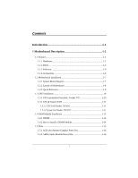
Contents Introduction 1-1 1 Motherboard Description 1-2 1.1 Features 1-2 1.1.1 Hardware 1-2 1.1.2 BIOS 1-6 1.1.3 Software 1-6 1.1.4 Accessories 1-6 1.2 Motherboard Installation 1-7 1.2.1 System Block Diagram 1-7 1.2.2 Layout of Motherboard 1-8 1.2.3 Quick Reference 1-9 1.3 CPU - Biostar M6VCT | M6VCT user's manual - Page 4
Contents 1.5.3 ISA (Industry Standard Architecture) Slot 1-16 1.5.4 PCI (Peripheral Component Interconnect) Slots 1-16 1.6 Connectors, Headers & Jumpers 1-17 1.6.1 Front Panel Connector: JPANEL1 1-17 1.6.1 Front Panel Connector: JPANEL1 1-18 1.6.2 ATX 20-pin Power Connector: JATXPWR1 1-20 - Biostar M6VCT | M6VCT user's manual - Page 5
Telephony Audio Header: JTAD1 (Optional 1-31 2. BIOS Setup 2-1 2.1 Main Menu 2-3 2.2 Standard CMOS Features 2-6 2.3 Advanced BIOS Features 2-9 2.4 Advanced Chipset Features 2-13 2.5 User Password 2-35 2.12 Save & Exit Setup 2-37 2.13 Exit Without Saving 2-38 3. Trouble Shooting 3-1 iii - Biostar M6VCT | M6VCT user's manual - Page 6
AMR Slot to support the solution of high performance, low cost modem. It is ideal for multi-tasking and fully supports MS-DOS, Windows 3x, Windows NT, Windows 2000, Windows ME, Novell, Windows 9x, UNIX, SCO UNIX and LINUX etc. This manual explains how to install the motherboard for operation. 1-1 - Biostar M6VCT | M6VCT user's manual - Page 7
Chapter 1 Motherboard Description 1 Motherboard Description 1.1 Features 1.1.1 Hardware CPU − The modules. − Supports synchronous DRAM (3.3V). − Supports a maximum memory size of 1.5GB with SDRAM. − 133MHz Bus frequency. Green Function − Supports power management operation via BIOS. − Power - Biostar M6VCT | M6VCT user's manual - Page 8
Chapter 1 Motherboard Description BUS Slots − Provide one (2X/4X)AGP slot and one/two 16-bit ISA Bus slots. − Four / Five 32-bit PCI bus master slots. − PCI V2.2 compliant. PCI Enhanced IDE Built-in onboard − Supports 4 IDE hard disk drives. − Supports Mode 4, bus master mode, high performance - Biostar M6VCT | M6VCT user's manual - Page 9
Chapter 1 Motherboard Description − 4 analog line-level stereo input with 5-bit volume control : 20ohm driving capability (ALC2001A). − External Amplifier power down capability. Power Management − Supports both ACPI (Advanced and Configuration and Power Interface) and legacy (APM) power management - Biostar M6VCT | M6VCT user's manual - Page 10
Chapter 1 Motherboard Description − Thermal alarm on either external or any combination of two internal physical layer transceivers with optional over-current detection status on USB inputs. − Keyboard and mouse support. Platform − ATX Form Factor. Dimension − 19.1 cm X 30.6 cm (W x L). - Biostar M6VCT | M6VCT user's manual - Page 11
Chapter 1 Motherboard Description (3)LRU replacement scheme. (4)Independent GART lookup control for host /AGP /PCI master accesses. − Windows 95 OSR-2 VXD and integrated Windows 98 / NT2000 /WINNT miniport driver support. 1.1.2 BIOS BIOS − AWARD legal & user-friendly BIOS. − Supports PnP functions - Biostar M6VCT | M6VCT user's manual - Page 12
2X/4X VIA VT82C694X/T M E M O RY 3 DIMM PCI BUS US B US B VT82C686B USB USB ISA BUS P CI P CI P CI P CI P CI FLASH BIOS Serial Port X2/ Parallel Port X1/ Game Port X1 ISA M6VCT ATX SUPPORTS 3 DIMMS SUPPORTS 1 4X AGP,5 PCI,1 AMR , 1 ISA SUPPORTS FRONT USB * 2 SUPPORTS STR FUNCTION 1-7 - Biostar M6VCT | M6VCT user's manual - Page 13
Description 1.2.2 Layout of Motherboard Model No.M6VCT JKBMS1 KB & Mouse JUSB1 USB JCOM1 JPRNT1 CPU JATXPWR1 Socket 370 DIMM3 DIMM2 DIMM1 PRIMARY IDE CONN. SECONDARY IDE CONN. FLOPPY DISK CONN. COM1 Parallel - Biostar M6VCT | M6VCT user's manual - Page 14
Chapter 1 1.2.3 Quick Reference I H GF E DC Motherboard Description B A SR Q P O N M L KJ A. Front Audio Header (JAUDIO1) J. CPU Fan Header (JCFAN1) B. Back panel I/O Connectors K. DIMMs (DIMM1-3) C. AMR BUS Slot (AMR1) L. ATX Power Connector (JATXPWR1) D. CD - Biostar M6VCT | M6VCT user's manual - Page 15
Chapter 1 Motherboard Description 1.3 CPU Installation 1.3.1 CPU Installation Procedure: Socket 370 Socket 370 1. Pull the lever sideways away from the socket then raise the lever up to a 90- - Biostar M6VCT | M6VCT user's manual - Page 16
Chapter 1 1.3.2 CPU & System FAN JCFAN1 1 Motherboard Description JSFAN1 1 1.3.2.1 CPU FAN Header: JCFAN1 Pin No. 1 2 3 Assignment Ground +12V Sense 1.3.2.2 System Fan Header: JSFAN1 Pin No. 1 2 3 Assignment Ground +12V Sense 1-11 - Biostar M6VCT | M6VCT user's manual - Page 17
Chapter 1 Motherboard Description 1.4 RAM Module Installation 1.4.1 DIMM DRAM Access Time : 3.3V Unbuffered SDRAM PC66, PC100 & PC133 Type required. DRAM Type : 8MB/16MB/32MB/64MB/128MB/256MB DIMM - Biostar M6VCT | M6VCT user's manual - Page 18
Chapter 1 Motherboard Description Total Memory Size (MB) 80 M 96 M 128 M 192 M 320 M 576 M 1080 M 144 M 160 M 192 M 256 M 384 M 640 M 1152 M 272 M 288 M 320 M 384 M 512 M 768 M - Biostar M6VCT | M6VCT user's manual - Page 19
Chapter 1 Motherboard Description 1.4.2 How to install a DIMM Module Single Sided DIMM Double Sided DIMM 1. The DIMM socket has a " Plastic Safety Tab" and the DIMM memory module has - Biostar M6VCT | M6VCT user's manual - Page 20
and connect them to the system bus. Expansion slots are a means of adding or enhancing the motherboard's features and capabilities. With these efficient facilities, you can increase the motherboard's capabilities by adding hardware that performs tasks that are not part of the basic system. AMR - Biostar M6VCT | M6VCT user's manual - Page 21
in video facilities and therefore requires a video card for one of the expansion slots. Your monitor will attach directly to that video card. This motherboard supports video cards for PCI and ISA slots but is also equipped with an Accelerated Graphics Port (AGP PRO). An AGP card will take advantage - Biostar M6VCT | M6VCT user's manual - Page 22
Chapter 1 Motherboard Description 1.6 Connectors, Headers & Jumpers The connectors, headers and jumpers introduced below provide you lots of capabilities such as power supply, front panel signal revelation, IDE - Biostar M6VCT | M6VCT user's manual - Page 23
LED Power-on Button IrDA Connector SPK (Speaker Connector) An offboard speaker can be installed on the motherboard as a manufacturing option. An offboard speaker can be connected to the motherboard at the front panel connector. The speaker (onboard or offboard) provides error beep code information - Biostar M6VCT | M6VCT user's manual - Page 24
momentary SPST switch. This switch is usually open and when closed will cause the motherboard to reset and run the POST (Power On Self Test). POW-LED ( . APM (Advanced Power Management) must be enabled in the system BIOS and the APM driver must be loaded. PWR (Power Button) This connector can be - Biostar M6VCT | M6VCT user's manual - Page 25
Ring Wake-Up and Soft Power Off are supported on this motherboard. This power connector supports instant power-on functionality, which means that CD-ROM, a 120MB Floppy (reserved for future BIOS) and other devices to IDE1 and IDE2. These connectors support the IDE hard disk cable provided. • IDE1 - Biostar M6VCT | M6VCT user's manual - Page 26
1.6.4 Floppy Disk Connector: FDD1 The motherboard provides a standard floppy disk connector (FDC) that supports 360K, 720K, 1.2M, 1.44M and 2.88M floppy disk types. This connector supports the provided floppy drive ribbon cables. 1.6.5 Wake On LAN Header: JWOL1 Pin No. 1 2 3 Assignment - Biostar M6VCT | M6VCT user's manual - Page 27
Chapter 1 Motherboard Description 1.6.6 Clear CMOS Jumper: JCMOS1 JCMOS1 1 3 1-2 Closed 1 3 2-3 Closed Assignment Normal Operation (default) Clear CMOS Data Remove AC power line JCMOS1 (2-3) closed Wait five seconds JCMOS1 (1-2) - Biostar M6VCT | M6VCT user's manual - Page 28
Keyboard COM1 JCOM1 COM2 JCOM2 Front Line In Mic Speaker In Out JSPKR1 JLIN1 JMIC1 1.7.1 PS/2 Mouse / Keyboard Connector: JKBMS1 The motherboard provides a standard PS/2 mouse / Keyboard mini DIN connector for attaching a PS/2 mouse. You can plug a PS/2 mouse / Keyboard directly into this - Biostar M6VCT | M6VCT user's manual - Page 29
PS/2 Mouse / Keyboard Connectors Pin 1 2 3 4 5 6 Assignment Data No connect Ground +5 V (fused) Clock No connect 1.7.2 USB Connector: JUSB1 The motherboard provides a OHCI (Open Host Controller Interface) Universal Serial Bus Roots for attaching USB devices such as: keyboard, mouse and other USB - Biostar M6VCT | M6VCT user's manual - Page 30
Chapter 1 Motherboard Description 1.7.3 Serial and Parallel Interface Ports This system comes equipped with two serial ports and one parallel port. Both types of interface ports will be - Biostar M6VCT | M6VCT user's manual - Page 31
Chapter 1 Motherboard Description 1.7.3.2 Connectivity The serial ports can be used in many ways, and it may be necessary to become familiar with the pinout diagram. The following - Biostar M6VCT | M6VCT user's manual - Page 32
Chapter 1 Motherboard Description 1.7.3.3 Parallel Interface Port: JPRNT1 Unlike the serial ports, parallel interface port has been standardized and should not present any difficulty interfacing peripherals to your - Biostar M6VCT | M6VCT user's manual - Page 33
Chapter 1 Motherboard Description 1.7.4 Game (Joystick) Port Connector: JGAME1 This connector allows you to connect a joystick or game pad for playing computer games. Also, you may play or - Biostar M6VCT | M6VCT user's manual - Page 34
Chapter 1 1.7.6 Audio Subsystem Motherboard Description 12 9 JAUDIO1 1 JCDIN2 1 JTAD1 1 JCDIN1 1-29 - Biostar M6VCT | M6VCT user's manual - Page 35
Chapter 1 Motherboard Description 1.7.6.1 CD-ROM Audio-In Header: JCDIN1 Pin No. 1 2 3 4 Assignment Right Channel Input Ground Ground Left Channel Input 1.7.6.2 CD-ROM Audio-In Header: JCDIN2 Pin - Biostar M6VCT | M6VCT user's manual - Page 36
Chapter 1 Motherboard Description 1.7.6.4 Telephony Audio Header: JTAD1 (Optional) Pin No. 1 2 3 4 Assignment PHONE_IN Ground Ground MONO_OUT 1-31 - Biostar M6VCT | M6VCT user's manual - Page 37
-tuning of the chipset controlling the entire system. The rest of this manual is intended to guide you through the process of configuring your system using Setup. Plug and Play Support These AWARD BIOS supports the Plug and Play Version 1.0A specification. ESCD (Extended System Configuration Data - Biostar M6VCT | M6VCT user's manual - Page 38
Component Interconnect) local bus specification. Please see the Intel technical documentation for additional information. DRAM Support SDRAM (Synchronous DRAM) are supported. Supported CPUs This AWARD BIOS support single Intel CPU. Using Setup In general, you use the arrow keys to highlight items - Biostar M6VCT | M6VCT user's manual - Page 39
to accept and enter the sub-menu. !! WARNING !! The information about BIOS defaults on manual (Figure 1,2,3,4,5,6,7,8,9) is just for reference, please refer to the BIOS installed on board, for update information. Figure 1. Main Menu CMOS Setup Utility-Copyright (C ) 1984-2000 Award Software - Biostar M6VCT | M6VCT user's manual - Page 40
likely to configure a workable computer when something is wrong. If you cannot boot the computer successfully, select the BIOS Setup options and try to diagnose the problem after the computer boots. These settings do not provide optimal performance. Set Supervisor Password Change, set, or disable - Biostar M6VCT | M6VCT user's manual - Page 41
Chapter 2 BIOS Setup Set User Password You can specify both a User and a Supervisor password. When you select either password option, you are prompted for a 1-6-character password. Enter - Biostar M6VCT | M6VCT user's manual - Page 42
Chapter 2 BIOS Setup 2.2 Standard CMOS Features The items in Standard CMOS Setup Menu are divided into 10 categories. Each category includes no, one or more than one - Biostar M6VCT | M6VCT user's manual - Page 43
Chapter 2 BIOS Setup Main Menu Selections This table shows the selections that you can make on the Main Menu. Item Date Options MM DD YYYY IDE Primary - Biostar M6VCT | M6VCT user's manual - Page 44
Options All Errors No Errors All, but Keyboard All, but Diskette All, but Disk/Key N/A N/A N/A Description Select the situation in which you want the BIOS to stop the POST process and notify you. Displays the amount of conventional memory de-tected during boot up. Displays the amount of extended - Biostar M6VCT | M6VCT user's manual - Page 45
function is enabled Swap Floopy Drive Disabled and someone attempt to Boot Up Numlock Status On write data into this Gate A20 Option Fast area, BIOS will show a Security Option Setup warning message on OS Select For DRAM > 64 MB Non-OS2 screen and alarm beep Report No FDD For WIN - Biostar M6VCT | M6VCT user's manual - Page 46
Warning feature for IDE Hard Disk boot sector protection. If this function is enabled and someone attempts to write data into this area, BIOS will show a warning message on screen and alarm beep. Disabled (default) No warning message appears when anything attempts to access the boot sector - Biostar M6VCT | M6VCT user's manual - Page 47
First /Second/Third/Other Boot Device These BIOS attempts to load the operating system from the devices in the sequence selected in these items. The Choices: Floppy, LS/ZIP, HDD-0, SCSI, HDD-1, HDD-2, - Biostar M6VCT | M6VCT user's manual - Page 48
), OS2. Report No FDD For WIN 98 Whether report no FDD for Win 98 or not. The Choices: Yes, No (default). Video BIOS Shadow Determines whether video BIOS will be copied to RAM for faster execution. Enabled (default) Optional ROM is enabled. Disabled Optional ROM is disabled. C8000 - CFFFF - Biostar M6VCT | M6VCT user's manual - Page 49
Chapter 2 BIOS Setup 2.4 Advanced Chipset Features This section allows you to AGP Driving Control Auto X AGP Driving Value EC OnChip USB Enabled OnChip USB2 Enabled USB Keyboard Support Disabled OnChip Sound Auto OnChip Modem Auto Memory ECC Check Disabled : Move Enter :Select +/-/ - Biostar M6VCT | M6VCT user's manual - Page 50
Chapter 2 BIOS Setup DRAM Clock When synchronous DRAM is installed, the number of clock AGP Driving Control The option determines the AGP Output Buffer Drive Strength. The Choices: Auto (default), Manual. AGP Driving Value The option determines the AGP Output Buffer Drive Strength. The Choice: EC ( - Biostar M6VCT | M6VCT user's manual - Page 51
BIOS Setup USB Keyboard Support Select Enabled if your system contains an Universal Serial Bus (USB) controller and you have an USB keyboard. The Choices: Disabled (default), Enabled. OnChip Sound Selecting Enabled allows caching of the system BIOS caching of the video BIOS, resulting in better - Biostar M6VCT | M6VCT user's manual - Page 52
Chapter 2 BIOS Setup 2.5 Integrated Peripherals Figure 5. Integrated Peripherals CMOS Setup Utility-Copyright (C ) 1984-2000 Award Software Integrated Peripherals On-Chip IDE Channel 0 On-Chip IDE Channel 1 IDE - Biostar M6VCT | M6VCT user's manual - Page 53
the operating environment includes a DMA drive (Windows 95 OSR2 or a third party IDE bus master driver). If your hard drive and your system software both support Ultra DMA/33, select Auto to enable BIOS support. The Choices: Auto (default), Disabled. Init Display First This item allows you decide to - Biostar M6VCT | M6VCT user's manual - Page 54
Chapter 2 BIOS Setup IDE HDD Block Mode Block mode is also called block transfer, multiple commands, or multiple sector read/write. If your IDE hard drive supports block mode (most new drives do), select Enabled for automatic detection of the optimal number of block mode (most new drives do), - Biostar M6VCT | M6VCT user's manual - Page 55
Chapter 2 BIOS Setup Onboard Parallel Port This item allows you to determine access buffered port Fast, buffered, Bidirectional Port. Select Normal unless you are certain your hardware and software both support EPP or ECP mode. The Choices: Normal (default), ECP, ECP/EPP,EPP. ECP Mode Use DMA - Biostar M6VCT | M6VCT user's manual - Page 56
Chapter 2 BIOS Setup SB DMA Select Change the SoundBlaster Pro direct memory access setting. MPU-401 Enable or Disable MPU-401 option. MPU-401 I/O Address Change the SoundBlaster Pro MPU-401 I/O address. Game Port (200-207H) Change the joystick connects port address. 2-20 - Biostar M6VCT | M6VCT user's manual - Page 57
Chapter 2 BIOS Setup 2.6 Power Management Setup The Power Management Setup allows you to configure you system to most effectively save energy while operating in a manner consistent with - Biostar M6VCT | M6VCT user's manual - Page 58
Chapter 2 BIOS Setup Power Management Option This category allows you to select the type (or degree) of power saving and is directly related to the following modes: 1. - Biostar M6VCT | M6VCT user's manual - Page 59
APM The Choices: No Yes (default) System BIOS will ignore APM when power Management is on. System Bios will wait for APM's prompt before it synchronization ports and write blanks to the video buffer. DPMS Support Initial display power management signaling. Blank Screen This option only - Biostar M6VCT | M6VCT user's manual - Page 60
Chapter 2 BIOS Setup Soft-Off by PWRBTN Pressing the power button for more had lost power previously without any subsequent manual intervention. There are 3 sources that provide current to the CMOS area that retains these Power-On instructions; the motherboard battery (3V), the Power Supply (5VSB - Biostar M6VCT | M6VCT user's manual - Page 61
Chapter 2 BIOS Setup Doze Mode / Suspend Mode The Doze Mode, and Suspend Mode fields set the Period of time after which each of these modes activate. At - Biostar M6VCT | M6VCT user's manual - Page 62
Chapter 2 BIOS Setup RTC Alarm Resume When "Enabled", you can set the date and time at which the RTC (real-time clock) alarm awakens the system from - Biostar M6VCT | M6VCT user's manual - Page 63
Disabled Enabled Enabled Item Help Menu Level Select Yes if you are using a Plug and Play capable operating system Select NO if you need the BIOS to configure non-boot devices : Move Enter :Select +/-/PU/PD :Value F10 :Save ESC :Exit F1 :General Help F5 :Previous Values F6 :Fail-Safe Defaults - Biostar M6VCT | M6VCT user's manual - Page 64
Configuration Data The system BIOS supports the PnP feature so update ESCD to the memory locations. These locations (4K) are reserved at the system BIOS. If Disabled (default) is chosen, the system's ESCD will update be shown on the screen only if "Manual" is chosen for the Resources Controlled By - Biostar M6VCT | M6VCT user's manual - Page 65
The Choices: Disabled (default), Enabled. Resources Controlled By By Choosing "Auto" the system BIOS will detect the system resources and automatically assign the relative IRQ and DMA channel for each peripheral. By Choosing "Manual", the user will need to assign IRQ & DMA for add-on cards. Be sure - Biostar M6VCT | M6VCT user's manual - Page 66
Chapter 2 BIOS Setup Assign IRQ For VGA Lets the user choose which IRQ to assign for the VGA. The Choices: Enabled (default), Disabled. Assign IRQ For USB Lets the user choose which IRQ to assign for USB. The Choices: Enabled (default), Disabled. 2-30 - Biostar M6VCT | M6VCT user's manual - Page 67
Chapter 2 BIOS Setup 2.8 PC Health Status Figure 8. Frequency/Voltage Control CMOS Setup Utility-Copyright (C ) 1984-2000Award Software PC Health Status Show H/W Monitor in POST Current CPU Temp. - Biostar M6VCT | M6VCT user's manual - Page 68
Chapter 2 BIOS Setup System FAN Speed These fields display the current speed of up to CPU and System fans, if your computer contains a monitoring system. Current Vcore, +2.5V, +3.3V, +5.0V, +12.0V Detects System Voltage automatically. 2-32 - Biostar M6VCT | M6VCT user's manual - Page 69
Chapter 2 BIOS Setup 2.9 Frequency Control Figure 9. Frequency / Clock Control CMOS Setup Utility-Copyright (C ) 1984-2000 Award Software Frequency / Clock Control CPU Vcore Select CPU Host/PCI/Clock - Biostar M6VCT | M6VCT user's manual - Page 70
9. Load Optimized Defaults CMOS Setup Utility-Copyright (C ) 1984-2000 Award Software Standard CMOS Features Frequency Control Advanced BIOS Features Advanced Chipset Features Load Optimized Defaults Set Supervisor Password Integrated PeriphLeoraalds Optimized DefauSltest U(Ys/eNr )P?asNsword - Biostar M6VCT | M6VCT user's manual - Page 71
Password Power ManagementESnetuepr Password : Save & Exit Setup PnP/PCI Configurations PC Health Status Exit Without Saving Esc : Quit F9: Menu in BIOS F10 : Save & Exit Setup : Select Item Change / Set / Disable Password When you select this function, the following message will appear at - Biostar M6VCT | M6VCT user's manual - Page 72
If you select "System" at the Security Option of BIOS Features Setup Menu, you will be prompted for the password every time the system is rebooted or any time you try to enter Setup. If you select "Setup" at Security Option of BIOS Feature Setup Menu, you will be prompted only when - Biostar M6VCT | M6VCT user's manual - Page 73
User Password Power ManagemenStASVetEupto CMOS and ESxaivte(Y&/NEx)it?SYetup PnP/PCI Configurations Exit Without Saving PC Health Status Esc : Quit F9: Menu in BIOS F10 : Save & Exit Setup : Select Item Save Data to CMOS Type "Y" will quit the Setup Utility and save the user setup value to - Biostar M6VCT | M6VCT user's manual - Page 74
Setup Set User Password PnP/PCI ConfigQuruatiitonWsithout Saving (YS/aNv)e?&NExit Setup PC Health Status Exit Without Saving Esc : Quit F9: Menu in BIOS F10 : Save & Exit Setup Abandon all Datas : Select Item Type "Y" will quit the Setup Utility without saving to RTC CMOS RAM. Type " N" will - Biostar M6VCT | M6VCT user's manual - Page 75
Trouble Shooting 3. Trouble Shooting PROBLEM socket are OK, but system is still dead. Contact technical support. Faulty wall outlet; circuit Plug in device known to Use Memory DIMM is partially dislodged from the slot on the motherboard. Turn off computer. Using even pressure on Take cover - Biostar M6VCT | M6VCT user's manual - Page 76
Chapter 3 Trouble Shooting PROBLEM System does not boot from hard disk drive, can be Damaged hard disk or disk controller. Format hard disk; if Contact technical unable to do so the hard support. disk may be defective. Hard disk directory or FAT is scrambled. Run the FDISK program, Backing up - Biostar M6VCT | M6VCT user's manual - Page 77
Trouble Shooting PROBLEM Error the configuration program. Replace any incorrect information. Review system's equipment . Make sure correct information PROBLEM DIAGNOSIS SOLUTION Check the power connectors to monitor and to system. Make sure monitor is connected to display card. See instructions - Biostar M6VCT | M6VCT user's manual - Page 78
Chapter 3 Trouble Shooting PROBABLE CAUSE Memory problem. Computer virus. PROBLEM DIAGNOSIS SOLUTION Reboot computer. Reinstall memory, make sure that all memory modules are installed in correct sockets. Use anti-virus programs to detect and clean viruses. PROBLEM Screen goes blank - Biostar M6VCT | M6VCT user's manual - Page 79
Trouble Shooting No display on screen. PROBABLE CAUSE Faulty Monitor. CMOS incorrectly set up. C: drive failure. PROBABLE CAUSE Hard drive cable not connected properly. PROBLEM DIAGNOSIS SOLUTION If possible, connect monitor to another system. If no color replace monitor. Call technical support - Biostar M6VCT | M6VCT user's manual - Page 80
Chapter 3 Trouble Shooting PROBLEM Missing operating system on hard drive. PROBABLE CAUSE CMOS setup has been changed. DIAGNOSIS SOLUTION Run setup and select correct drive type. PROBLEM Certain keys do not function. PROBABLE CAUSE Keys jammed or defective. DIAGNOSIS SOLUTION Replace - Biostar M6VCT | M6VCT user's manual - Page 81
08/16/2001 MADE IN TAIWAN R.O.C.
-
 1
1 -
 2
2 -
 3
3 -
 4
4 -
 5
5 -
 6
6 -
 7
7 -
8
-
9
-
10
-
11
-
12
-
13
-
14
-
15
-
16
-
17
-
18
-
19
-
20
-
21
-
22
-
23
-
24
-
25
-
26
-
27
-
28
-
29
-
30
-
31
-
32
-
33
-
34
-
35
-
36
-
37
-
38
-
39
-
40
-
41
-
42
-
43
-
44
-
45
-
46
-
47
-
48
-
49
-
50
-
51
-
52
-
53
-
54
-
55
-
56
-
57
-
58
-
59
-
60
-
61
-
62
-
63
-
64
-
65
-
66
-
67
-
68
-
69
-
70
-
71
-
72
-
73
-
74
-
75
-
76
-
77
-
78
-
79
-
80
-
81
 |
 |

M6VCT
Federal Communications Commission
(F.C.C) Statement
•
This device complies with Part 15 of the FCC Rules. Operation of
this device is subject to the following two conditions: (1) this device may
not cause harmful interference, and (2) this device must accept any
interference received, including interference that may cause undesired
operation.
•
Accessories: This device has been tested and found to comply with
the limits of a Class B digital device, the accessories associated with this
equipment are as follows:
1. Shielded serial cable. (Can be obtained from multiple retail outlets)
2. Shielded printer cable. (Can be obtained from multiple retail outlets)
3. Shielded video cable. (Can be obtained from multiple retail outlets)
4. Shielded power cord. (Provided by manufacturer)
These accessories are required to ensure compliance with FCC Rules. It is
the responsibility of the user to provide and use these accessories
properly.
•
This equipment has been tested and found to comply with the limits
of a Class B digital device, pursuant to Part 15 of the FCC Rules. These
limits are designed to provide reasonable protection against harmful
interference in a residential installation. This equipment generates, uses
and can radiate radio frequency energy and, if not installed and used in
accordance with the instructions, may cause harmful interference to radio
communications. There is no guarantee that interference will not occur in
a particular installation. If this equipment does cause harmful interference
to radio or television reception, which can be determined by turning the
equipment off and on, you are encouraged to try to correct the
interference by one or more of the following measures:
1. Reorient / relocate the receiving antenna.
2. Increase the separation between the equipment and receiver.
3. Connect the equipment into an outlet on a circuit different from that to
which the receiver is connected.