Bosch HMV3051U Installation Instructions
Bosch HMV3051U - 300 Series - Microwave Manual
 |
UPC - 825225879046
View all Bosch HMV3051U manuals
Add to My Manuals
Save this manual to your list of manuals |
Bosch HMV3051U manual content summary:
- Bosch HMV3051U | Installation Instructions - Page 1
Installation Instructions Instrucciones de Instalación 3Ć30 31Ć59 Microwave oven Model: HMV 3051 U HMV 3061 U HMV 3021 U - Bosch HMV3051U | Installation Instructions - Page 2
- Bosch HMV3051U | Installation Instructions - Page 3
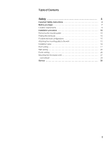
Installation procedure 10 Removing the mounting plate 10 Finding the wall studs 10 Possible wall stud configurations 10 Attaching the mounting plate to the wall 12 Installation types 16 Roof venting 17 Wall venting 20 Room venting 25 Mounting the microwave oven 27 Hood exhaust 29 Service - Bosch HMV3051U | Installation Instructions - Page 4
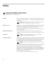
Important Examine your oven Appliance handling safety Intended Use Grounding Instructions SAVE THESE INSTRUCTIONS FOR THE LOCAL ELECTRICAL INSPECTOR'S USE. LEAVE THESE INSTRUCTIONS WITH THE APPLIANCE AFTER INSTALLATION IS COMPLETE. ř WARNING:ĄIf the information in this manual is not followed - Bosch HMV3051U | Installation Instructions - Page 5
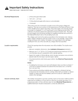
SAVE THESE INSTRUCTIONS Electrical Support for weight of 150 lbs (68 kg), which includes microwave oven and items placed inside the microwave oven and upper cabinet. D Grounded electrical outlet inside upper cabinet. (See Electrical Requirements) section. Notes: D If installing the microwave oven - Bosch HMV3051U | Installation Instructions - Page 6
of fire, use only metal ductwork. ř WARNING:ĄDo not repair or replace any part of the appliance unless specifically recommended in the manuals. Never modify or alter the construction of the appliance. Improper installation, service or maintenance can cause injury or property damage. Refer to this - Bosch HMV3051U | Installation Instructions - Page 7
Before you begin Tools and parts needed D No.1 Phillips screwdriver D Pencil D Ruler or tape measure and straight edge D Drill with 3/16" (5 mm),1/2 (13 mm) and cut damper) D Scissors (to cut top cabinet template) D Filler blocks or scrap wood pieces (for recessed bottom cabinet installations) 7 - Bosch HMV3051U | Installation Instructions - Page 8
included You will find the installation hardware contained in packet with the unit. Check to make sure you have all these parts: DA DB DC SelfĆAligning Machine Screws - ¼"Ć28 plate (attached to the back of microwave oven) D Aluminum grease filters D Charcoal filter (attached to microwave oven) 8 - Bosch HMV3051U | Installation Instructions - Page 9
Location requirements Installation dimensions Grounded outlet (Inside cabinet above the oven) Product dimensions 9 - Bosch HMV3051U | Installation Instructions - Page 10
must be connected to at least one wall stud. If no wall studs exist within the cabinet opening, do not install the microwave oven. 1. Locate the edges of the wall studs within the cabinet opening by using: D a stud finder or D a hammer (tapping lightly across the mounting surface to find a - Bosch HMV3051U | Installation Instructions - Page 11
No wall studs at corner holes Wall stud at one corner hole Note:ĄIf wall stud is within 6¼" (159 mm) of the vertical centerline, only Room Venting (recirculation) or Roof Venting installations can be done. 11 - Bosch HMV3051U | Installation Instructions - Page 12
and draw a fith circle to line up with the stud. It is important to use at least one wood screw mounted firmly in a stud to support the weight of the microwave. 12 - Bosch HMV3051U | Installation Instructions - Page 13
Figure 1 - Flat or frame recessed bottom cabinet Figure 2 - Recessed bottom cabinet with front overhang 5. Set the mounting plate aside 6. Drill holes on the circles: D 3/16" (5 mm) holes for wood screws (stud) D 5/8" (16 mm) holes for toggle bolts (no stud) 13 - Bosch HMV3051U | Installation Instructions - Page 14
Attaching the mounting plate (no wall studs at corner holes) 1. Insert the bolts into the mounting plate through the holes designated. 2. Attach toggle wings from the back of the mounting plate onto each bolt. Leave enough space for toggle wings to go through the wall and to open. 3. Place the - Bosch HMV3051U | Installation Instructions - Page 15
Attaching the mounting plate (Wall stud at one corner hole) Attaching the mounting plate (Wall studs at both corner holes) 5. Check if the plate is properly centered, make sure it is level. 6. Securely tighten all screws, including the fifth wood screw in the bottom area of the mounting plate. 1. - Bosch HMV3051U | Installation Instructions - Page 16
Installation types ROOF VENTING proceed to page 17 WALL VENTING proceed to page 20 ROOM VENTING proceed to page 25 16 - Bosch HMV3051U | Installation Instructions - Page 17
. Note:ĄFor recessed cabinet bottom, trim the template edges so that it fits inside the recessed area. The template has trim lines to use as guides. 17 - Bosch HMV3051U | Installation Instructions - Page 18
hole is for the power supply cord. Note:ĄIf the cabinet is metal, use the nylon grommet around the opening to protect the cord. Adapting microwave blower 6. Cut out the shaded area E" using a saber or keyhole saw. 1. Remove and save the screws holding the blower motor and the blower plate. Lift - Bosch HMV3051U | Installation Instructions - Page 19
4. Replace the blower plate and secure with the srews removed in step 1. 3. 4. 5. Attach the exhaust adapter to the top of the blower plate by sliding it into the guides. Push in securely until it is in the locking tabs. Make sure the damper hinge swings freely. 5. Proceed on page 27. 19 - Bosch HMV3051U | Installation Instructions - Page 20
. Note:ĄFor recessed cabinet bottom, trim the template edges so that it fits inside the recessed area. The template has trim lines to use as guides. 20 - Bosch HMV3051U | Installation Instructions - Page 21
cutout area. The 12" x 4" (305 x 102 mm) cutout area must align with the wall damper vent (where the damper assembly will be installed) on the back of the microwave oven. Note:ĄCutout must be free of any obstructions so that the vent fits properly, and the damper hinge opens fully and swings freely - Bosch HMV3051U | Installation Instructions - Page 22
and put it aside. 2. Carefully pull out the blower unit and rotate 90º so that fan blade openings are facing out the top of the microwave 1. 2. 3. Rotate the blower unit counterclockwise 180º. 4. Gently remove the wires from the grooves. Reroute the wires through the grooves on other side of the - Bosch HMV3051U | Installation Instructions - Page 23
back into the opening. 6. Replace the blower plate and secure with the srews removed in Step 1. 5. 6. 7. Attach the exhaust adapter to the rear of the oven by sliding it into the guides. Push in securely until it is in the lower locking tabs. Make sure the damper hinge swings freely. 23 - Bosch HMV3051U | Installation Instructions - Page 24
7. Proceed on page 27. 24 - Bosch HMV3051U | Installation Instructions - Page 25
. Note:ĄFor recessed cabinet bottom, trim the template edges so that it fits inside the recessed area. The template has trim lines to use as guides. 25 - Bosch HMV3051U | Installation Instructions - Page 26
the power supply cord. Note:ĄIf the cabinet is metal, use the nylon grommet around the opening to protect the cord. Adapting microwave blower This microwave is shipped assembled for Room Venting Installation. The blower unit is already in place and must not to be adapted. Proceed on page 27. 26 - Bosch HMV3051U | Installation Instructions - Page 27
provide additional support for the bolts: D mark the center of each filler block and drill a \ (9,5 mm) diameter hole D align filler blocks over the three openings on top of the microwave oven and attach with masking tape (see Figure 1) Note:ĄUse at least two people to install the microwave oven. Do - Bosch HMV3051U | Installation Instructions - Page 28
Tighten center screw completely. 6. Tighten the outer two screws completely to the top of the microwave oven. Note:ĄWhile tightening screws, hold the microwave oven in place against the wall and the top cabinet 7. Install grease filters by sliding them into the side slots, then pushing up and toward - Bosch HMV3051U | Installation Instructions - Page 29
When venting exhaust to the oustside, hood exhaust ducts will be required. Read the following carefully. Note:ĄIt is important that venting be installed using the most direct route and with as few elbows as possible. This ensures clear venting of exhaust and helps prevent blockages. Also, make - Bosch HMV3051U | Installation Instructions - Page 30
ĆtoĆround transition adapter is used, first make sure the damper hinge of the microwave swings freely. If necessary, cut the damper to fit, using the tin snips, any vent hood. Service Contact our Service department if your appliance needs repair. Our central Customer Service Center (see below) - Bosch HMV3051U | Installation Instructions - Page 31
Contenido Seguridad 32 Instrucciones de seguridad importantes 32 Antes de empezar 35 Requisitos de ubicación 36 Procedimiento de instalación 37 Cómo retirar la placa de montaje 37 Cómo encontrar los montantes de pared 38 Posibles configuraciones de los montantes de pared 38 Cómo colocar la - Bosch HMV3051U | Installation Instructions - Page 32
:ĄSi no sigue la información de este manual exactamente, se puede ocasionar un incendio o se encuentra dañado, notifique al distribuidor de inmediato. No instale el horno si se encuentra dañado. Destruya el embalaje intentar tomar el electrodoméstico por la parte trasera o desde abajo. ř ATTENCION - Bosch HMV3051U | Installation Instructions - Page 33
Requisitos eléctricos No use un cable de extensión. Si el cable de alimentación del producto es demasiado corto, haga que un electricista calificado instale un receptáculo de tres ranuras. Este horno debe enchufarse en un circuito de 60 hertz por separado, con la capacidad eléctrica nominal que - Bosch HMV3051U | Installation Instructions - Page 34
:ĄNo repare ni cambie ninguna parte del electrodoméstico, a menos que se recomiende específicamente en los manuales. Nunca modifique ni altere la mantenimiento incorrectos pueden causar lesiones o daños materiales. Consulte este manual para su orientación. Remita todas las demás reparaciones a un - Bosch HMV3051U | Installation Instructions - Page 35
Antes de empezar Herramientas y piezas necesarias D Destornillador Phillips n.º 1 D Lápiz D Regla o cinta métrica y borde recto D Taladro con brocas de 3/16" (5 mm), 1/2" (13 mm) y 5/8" (16 mm) D Guantes D Sierra (recíproca, caladora o de punta) D Localizador de montantes o martillo D Gafas de - Bosch HMV3051U | Installation Instructions - Page 36
(para gabinetes de metal) Adaptador del escape Requisitos de ubicación No se muestran: D Plantilla del gabinete superior D Placa de montaje (sujetar a la parte posterior del horno de microondas) D Filtros de grasa de aluminio D Filtro de carbón (sujeta al horno de microondas) Dimensiones para la - Bosch HMV3051U | Installation Instructions - Page 37
Dimensiones del producto Procedimiento de instalación Cómo retirar la placa de montaje Advertencia:ĄPara evitar posibles daños a la superficie de trabajo o a la base del electrodoméstico, cubra la superficie de trabajo. 1. Retire cualquier elemento que haya quedado en la cavidad del horno de - Bosch HMV3051U | Installation Instructions - Page 38
:ĄEl horno de microondas debe conectarse, al menos, a un montante de pared. Si no hay montantes de pared en la abertura del gabinete, no instale el horno de microondas. 1. Ubique los bordes de los montantes de pared dentro del gabinete usando: D un localizador de montantes o D un martillo (dando - Bosch HMV3051U | Installation Instructions - Page 39
Montante de pared en uno de los orificios de las esquinas Montantes de pared en ambos orificios de las esquinas 39 - Bosch HMV3051U | Installation Instructions - Page 40
Cómo colocar la placa de montaje en la pared Cómo alinear la placa de montaje ř ATTENCION:ĄUse guantes para evitar cortarse los dedos con los bordes filosos. Advertencia:ĄAsegúrese de que la base del gabinete esté nivelada. 1. Trace una línea vertical en la pared, en el centro del espacio del - Bosch HMV3051U | Installation Instructions - Page 41
Figura 2 Ć Gabinete inferior empotrado con saliente frontal 5. Deje la placa de montaje a un costado 6. Perfore orificios en los círculos: D orificios de 3/16" (5 mm) para tornillos para madera (con montante) D orificios de 5/8" (16 mm) para pernos articulados (sin montante) Cómo colocar la placa de - Bosch HMV3051U | Installation Instructions - Page 42
2. Una las alas articuladas a cada perno desde la parte posterior de la placa de montaje. Deje espacio suficiente para que las alas articuladas atraviesen la pared y se abran. 3. Coloque la placa de montaje contra - Bosch HMV3051U | Installation Instructions - Page 43
esquinas) 1. Inserte los pernos y los tornillos para madera en la placa de montaje por los orificios designados. 2. Una las alas articuladas desde la parte posterior de la placa de montaje en cada perno. Deje espacio suficiente para que las alas articuladas atraviesen la pared y se abran. 3. Coloque - Bosch HMV3051U | Installation Instructions - Page 44
Tipos de instalación VENTILACIÓN DE TECHO continúe en la página 45 VENTILACIÓN DE PARED continúe en la página 48 VENTILACIÓN DE AMBIENTE continúe en la página 53 44 - Bosch HMV3051U | Installation Instructions - Page 45
Ventilación de techo Preparación del gabinete superior 1. Corte la alimentación eléctrica a la toma de corriente. 2. Retire todo el contenido del gabinete superior. 3. Pegue la PLANTILLA DEL GABINETE SUPERIOR a la superficie inferior con cinta. Asegúrese de que la línea central de la plantilla est - Bosch HMV3051U | Installation Instructions - Page 46
y déjela a un lado. 2. Retire el soplador con cuidado y gírelo 90º de modo que las aberturas de las hojas del ventilador miren hacia la parte superior del horno de microondas. 1. 2. 3. Vuelva a colocar el soplador en la abertura. ř ATTENCION:ĄNo tire del cableado del soplador ni lo estire. Aseg - Bosch HMV3051U | Installation Instructions - Page 47
4. Vuelva a colocar la placa del soplador y asegúrela con los tornillos que retiró en el paso 1. 3. 4. 5. Coloque el adaptador del escape en la parte superior de la placa del soplador deslizándolo por las guías. Empújelo firmemente hasta que quede en las lengüetas de bloqueo. Asegú - Bosch HMV3051U | Installation Instructions - Page 48
Ventilación de pared Preparación del gabinete superior 1. Corte la alimentación eléctrica a la toma de corriente. 2. Retire todo el contenido del gabinete superior. 3. Pegue la PLANTILLA DEL GABINETE SUPERIOR a la superficie inferior con cinta. Asegúrese de que la línea central de la plantilla est - Bosch HMV3051U | Installation Instructions - Page 49
Consulte Cómo colocar la placa de montaje en la pared) \ (10 mm) hacia abajo desde la parte superior de la placa de montaje. 2. Con una cinta métrica, mida 6" (152 mm) a pared (donde se instalará el conjunto del regulador) en la parte posterior del horno de microondas. Advertencia:ĄEl hueco no debe - Bosch HMV3051U | Installation Instructions - Page 50
del soplador y déjela a un lado. 2. Retire el soplador con cuidado y gírelo 90º de modo que las aberturas de las hojas del ventilador miren hacia la parte superior del horno de microondas. 1. 2. 3. Gire el soplador 180º hacia la izquierda. 50 - Bosch HMV3051U | Installation Instructions - Page 51
del otro lado de la unidad del soplador. Gire el soplador 90º de modo que las aberturas de las hojas del ventilador miren hacia la parte posterior del horno de microondas. 3. 4. ř ATTENCION:ĄNo tire del cableado del soplador ni lo estire. Asegúrese de que los cables no estén pellizcados y de - Bosch HMV3051U | Installation Instructions - Page 52
7. Coloque el adaptador del escape en la parte posterior del horno deslizándolo por las guías. Empújelo firmemente hasta que quede en las lengüetas de bloqueo inferiores. Asegúrese de que la bisagra reguladora se mueva libremente. 7. Continúe en la página 55. 52 - Bosch HMV3051U | Installation Instructions - Page 53
Ventilación de ambiente Preparación del gabinete superior 1. Corte la alimentación eléctrica a la toma de corriente. 2. Retire todo el contenido del gabinete superior. 3. Pegue la PLANTILLA DEL GABINETE SUPERIOR a la superficie inferior con cinta. Asegúrese de que la línea central de la plantilla - Bosch HMV3051U | Installation Instructions - Page 54
4. Perfore orificios de 3/8" (9.5 mm) en A", B" y C". ř ATTENCION:ĄUse gafas de seguridad al perforar orificios en la base del gabinete. 5. Cale el orificio de 2" (50.8 mm) en D". Este orificio es para el cable de alimentación eléctrica. Advertencia:ĄSi el gabinete es de metal, coloque la - Bosch HMV3051U | Installation Instructions - Page 55
relleno y perfore un orificio de \ (9.5 mm) de diámetro D alinee los bloques de relleno sobre las tres aberturas que se encuentran en la parte superior del horno de microondas y sujételos con cinta de enmascarar (ver Figura 1) Advertencia:ĄSe necesitan, al menos, dos personas para instalar el horno - Bosch HMV3051U | Installation Instructions - Page 56
6. Ajuste completamente los dos tornillos de los extremos a la parte superior del horno de microondas. Advertencia:ĄAl ajustar los tornillos, sostenga el horno de microondas en su lugar contra la pared y el gabinete superior. 7. Instale filtros de grasa deslizándolos dentro de las ranuras laterales - Bosch HMV3051U | Installation Instructions - Page 57
Escape de campana Conexión del escape Longitud máxima del conducto Codos, transiciones, tapas de pared y techo, etc. Al ventilar el escape hacia el exterior, se necesitarán conductos del escape de campana. Lea detenidamente las siguientes instrucciones. Advertencia:ĄEs importante instalar la - Bosch HMV3051U | Installation Instructions - Page 58
Piezas de conductos Longitud equivalente x Adaptador de transición de rectangular a redondo* 5 pies (1.5 m) x Tapa de pared 40 pies (12.2 m) x Codo de 90º 10 pies (3 m) x Cantidad usada Longitud equivalente ( ) = pies o m ( ) = pies o m ( ) = pies o m Codo de 45º 5 pies (1.5 - Bosch HMV3051U | Installation Instructions - Page 59
Servicio técnico Si necesita reparar el electrodoméstico, llame a nuestro Departamento de Servicio Técnico. Nuestro Centro de Servicio al Cliente principal (vea a continuación) también se complacerá en brindarle la información sobre un centro cercano a su domicilio. Cuando llame a nuestro servicio - Bosch HMV3051U | Installation Instructions - Page 60
9000 423675 S B110289 0 5551 McFadden Ave., Huntington Beach, CA 92649 S1Ć800Ć944Ć2904 www.boschappliances.comE BSH Home Appliances Corporation 2008
-
 1
1 -
 2
2 -
 3
3 -
 4
4 -
 5
5 -
 6
6 -
 7
7 -
8
-
9
-
10
-
11
-
12
-
13
-
14
-
15
-
16
-
17
-
18
-
19
-
20
-
21
-
22
-
23
-
24
-
25
-
26
-
27
-
28
-
29
-
30
-
31
-
32
-
33
-
34
-
35
-
36
-
37
-
38
-
39
-
40
-
41
-
42
-
43
-
44
-
45
-
46
-
47
-
48
-
49
-
50
-
51
-
52
-
53
-
54
-
55
-
56
-
57
-
58
-
59
-
60
 |
 |

M5*+2:
HM%
30±1
$
HM%
3061
$
HM%
30²1
$
M/)85=’<+ 5<+4
I49³’22’³/54 I49³8;)³/549
3F30
I49³8;))/54+9 *+
I49³’2’)/D4
31F±´