Brother International BAS-326E Network Users Manual - English - Page 97
Reads 2DD data as 341A/342A data., Change X and Y scales.
 |
View all Brother International BAS-326E manuals
Add to My Manuals
Save this manual to your list of manuals |
Page 97 highlights
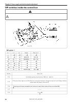
Chapter 6 Power supply and electrical parts adjustment s Turn the dial while pressing the STEP BACK switch to change the values. Turn the dial while pressing the STEP BACK switch to change the values. SW No. memo-30 Possible setting range Units 1 - 999 x 10ms Initial value 10 Explanation Time until feed mechanism starts moving after work clamp has lifted. memo-31 1 - 4 ---- 1 Changes the feed speed. 1 (Fast) ɹɹɹ4 (Slow) memo-32 1 - 7 Changes the possible sewing speed for a given stitch length. 1 (Fast) 7 (Slow) 1 (2,700/3 mm), 2 (2,600/3 mm), 3(2,500/3 mm), ---- 3 4 (2,300/3 mm), 5 (2,000/3 mm), 6 (1,800/3 mm), 7 (1,200/3 mm) Settings 1 and 2 are outside the warranty specification at the time of shipment from the factory.) memo-33 1 - 10 x 7.5° 5 Changes the feed timing 1 (Fast) ɹɹɹ5 (standard) ɹɹɹ10 (Slow) memo-34 1 - 5 ---- 0 Number of stitches sewn at 400 spm (10W speed) at sewing start memo-35 memo-36 memo-37 10 - 60 1 - 3 0 - 3 Xms ------- Solenoid ON time changes when work clamp is being 40 lowered (solenoid specifications only) 10 60 (Quiet) (High work clamp capacity) Solenoid ON time to raise presser foot is changed. 1 (Standard) 1ɹɹɹ3 (Upper limit) ç 1 (10 ms) 2 (20 ms) 3 (30 ms) Gear ratio is automatically corrected when 2DD data is read. 0: Follows the model specified in DIP switch C. 1: Reads 2DD data as 311A data. 3 2: Reads 2DD data as 326A data. 3: Reads 2DD data as 341A/342A data. [This function is available when panel PROM indication is PL-C or later.] memo-38 memo-39 1 - 20 0 - 11 X0.1S ---- Delay time from the point when the cassette is 1 clamped to the start of sewing when DIP switch A7 is Î ON during automatic sewing [Set value] 0: Sensor home position, 1: Center of sewing area, 2: Upper left of sewing area, 3: Lower left of sewing area, 4: Upper right of sewing area, 5: Lower right of sewing area, 6: Sewing start point, 7: Sewing end point, 8: Upper left of mask, 9: Lower left of mask, 10: Upper right of mask, 11: Lower right of mask [Procedure] 1. Select memory switch 39. 0 2. Change X and Y scales. 3. Step on start switch to return to home position, and sewing data can be created with specified scales. [Mask] Upper left ¡Mask is a rectangular frame of mask to cover the rounded edges of sewing data. ¡In the left figure, an oval is Lower left of mask sewing data, and the rectangle indicated with a broken line is the mask. Note indicates that these functions are available for software versions MN-C · MND · MN-F or later. BAS-311E.311EL.326E.326EL 89
-
 1
1 -
2
-
3
-
4
-
5
-
6
-
7
-
8
-
9
-
10
-
11
-
12
-
13
-
14
-
15
-
16
-
17
-
18
-
19
-
20
-
21
-
22
-
23
-
24
-
25
-
26
-
27
-
28
-
29
-
30
-
31
-
32
-
33
-
34
-
35
-
36
-
37
-
38
-
39
-
40
-
41
-
42
-
43
-
44
-
45
-
46
-
47
-
48
-
49
-
50
-
51
-
52
-
53
-
54
-
55
-
56
-
57
-
58
-
59
-
60
-
61
-
62
-
63
-
64
-
65
-
66
-
67
-
68
-
69
-
70
-
71
-
72
-
73
-
74
-
75
-
76
-
77
-
78
-
79
-
80
-
81
-
82
-
83
-
84
-
85
-
86
-
87
-
88
-
89
-
90
-
91
-
 92
92 -
 93
93 -
 94
94 -
 95
95 -
 96
96 -
 97
97 -
 98
98 -
 99
99 -
 100
100 -
 101
101 -
 102
102 -
103
-
104
-
105
-
106
-
107
-
108
-
109
-
110
-
111
-
112
-
113
-
114
-
115
-
116
-
117
-
118
-
119
-
120
-
121
-
122
-
123
-
124
-
125
-
126
-
127
-
128
-
129
-
130
-
131
-
132
-
133
-
134
-
135
-
136
-
137
-
138
-
139
-
140
-
141
-
142
-
143
-
144
-
145
-
146
-
147
-
148
-
149
-
150
 |
 |
