Brother International S-7200B Service Manual - Page 11
Using the LOCK key, 3-3. Setting the DIP switches
 |
View all Brother International S-7200B manuals
Add to My Manuals
Save this manual to your list of manuals |
Page 11 highlights
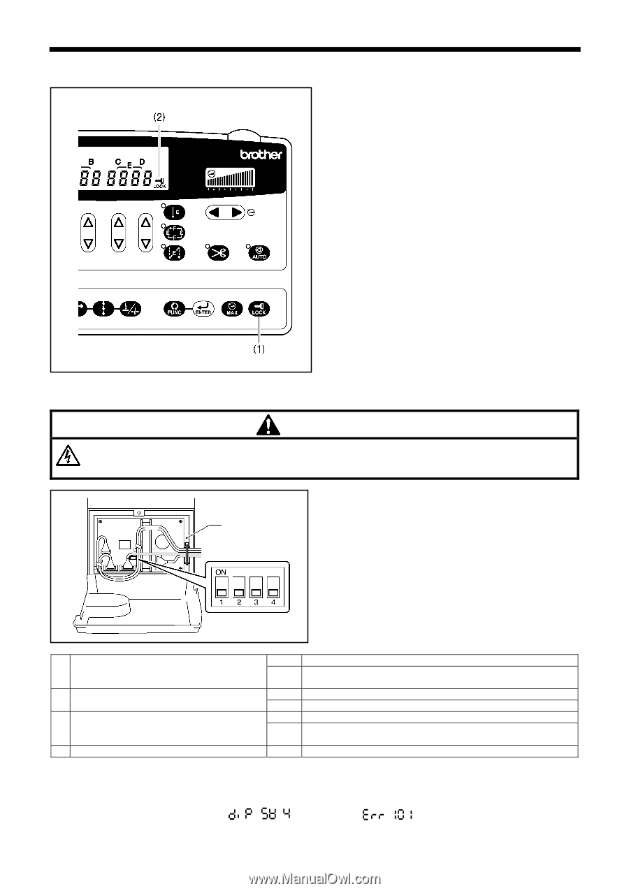
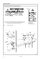
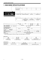
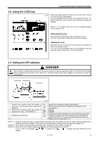
3-2. Using the LOCK key 3. FUNCTION SETTINGS (OPERATION PANEL) 1230B When the power switch is turned on, the LOCK key (1) turns on. (The icon (2) is illuminated.) The key operation that has been set using Function No. 101 will be disabled in order to prevent the accidental changing of settings. Refer to "3-5. Function List" (P.17) for the available settings for Function No. 101. Press down the LOCK key (1) for 2 seconds or more. The icon (2) will switch off and the lock will be released. When the icon (2) is switched off, press down the LOCK key (1) for 2 seconds or more. The icon (2) will illuminate and the key operation that has been set using Function No. 101 will be disabled. 3-3. Setting the DIP switches DANGER Wait at least 5 minutes after turning off the power switch and disconnecting the power cord from the wall outlet before opening the face plate of the control box. Touching areas where high voltages are present can result in severe injury. CConotnrotrloBl booxx 0655B Presser foot position when the treadle is ON 1 returned to the neutral position after thread trimming OFF 2 Presser foot lowering when the treadle is ON depressed to step 1. (See NOTE 2) OFF ON 3 Disabling the LOCK key OFF 4 Presser foot is lowered. (Export specification) Presser foot is kept raised. (Japanese specification only) (See NOTE 1.) Enabled Disabled The lock will not be released even if the LOCK key is pressed. Enabling or disabling of the key operation that has been set using Function No. 101 can be selected using the LOCK key. Always set to off. (See NOTE 3.) (NOTE 1) Once the knee lifter switch is used to lower the presser foot, the treadle can not be used to raise the presser foot while the machine is stopped; at this time, only the knee lifter is able to raise and lower the presser foot. (NOTE 2) The treadle unit should also be adjusted when using this function. (Refer to page 56.) (NOTE 3) When set to ON, treadle operation is disabled, so it should always be left at OFF. If set to ON, the messages " 「 " (green) and " " (orange) will flash alternately in the display. S-7200B 4
-
 1
1 -
2
-
3
-
4
-
5
-
 6
6 -
 7
7 -
 8
8 -
 9
9 -
 10
10 -
 11
11 -
 12
12 -
 13
13 -
 14
14 -
 15
15 -
 16
16 -
17
-
18
-
19
-
20
-
21
-
22
-
23
-
24
-
25
-
26
-
27
-
28
-
29
-
30
-
31
-
32
-
33
-
34
-
35
-
36
-
37
-
38
-
39
-
40
-
41
-
42
-
43
-
44
-
45
-
46
-
47
-
48
-
49
-
50
-
51
-
52
-
53
-
54
-
55
-
56
-
57
-
58
-
59
-
60
-
61
-
62
-
63
-
64
-
65
-
66
-
67
-
68
-
69
-
70
-
71
-
72
-
73
-
74
-
75
-
76
-
77
-
78
-
79
-
80
-
81
-
82
-
83
-
84
 |
 |