Brother International S-7200B Service Manual - Page 60
Control Box And Motor, Connector Cn6, Left_up_sw
 |
View all Brother International S-7200B manuals
Add to My Manuals
Save this manual to your list of manuals |
Page 60 highlights
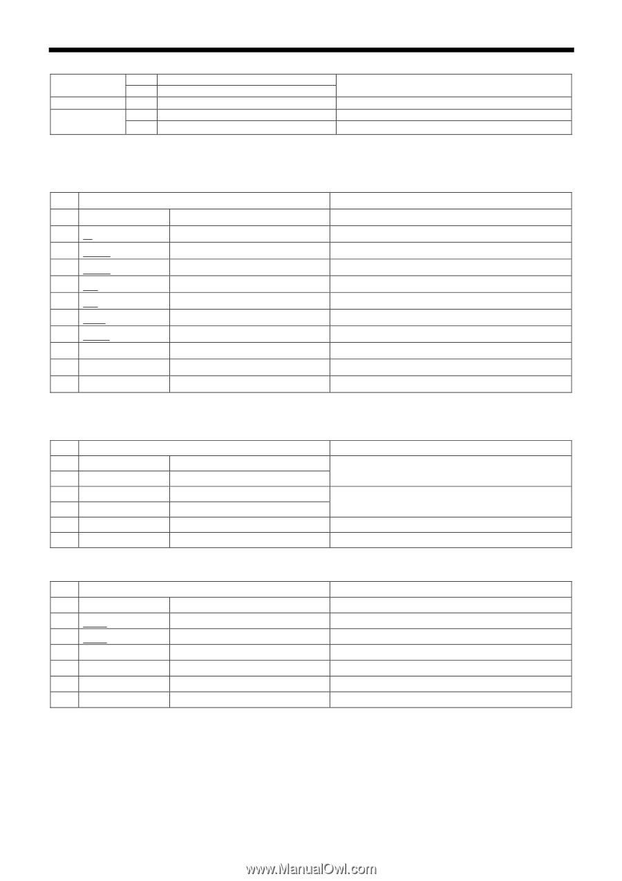
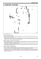
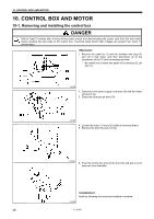
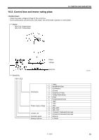
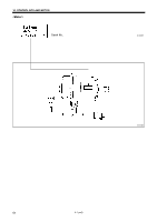
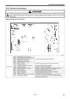
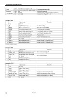
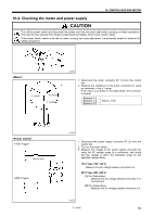
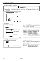
10. CONTROL BOX AND MOTOR Fuses DIP switch LED indicators F2 5A F1 5A DSW LD2 LD1 Solenoid power supply fuse (5A) Illumination lamp power supply fuse (5A) DSW Red LED Green LED For preventing overcurrent For function selection Indicates power supply circuit board problems. Indicates that the power is on. Connector CN6 1 +5V 2 IN 3 SPSP 4 STOP 5 ND 6 NU 7 ENG 8 STBY 9 S0V 10 ENC-A 11 ENC-B (*) Open collector output Signal name DC +5V Variable signal input Speed command input Operation prevention input Needle down signal output (*) Needle up signal output (*) Machine shaft sync signal (*) Operation signal output (*) 0V (GND) A phase signal output (*) B phase signal output (*) Remarks For stitch counting [Not used by the S-7200A] L level: Operation prevented L level: Needle down stop position L level: Needle up stop position 45 pulses/stitch H level: Operation in progress Encoder A phase (180 pulses/stitch) Encoder B phase (180 pulses/stitch) Connector CN9 1 +5V 2 UNTH_LED 3 UNTH_SW 4 S0V 5 IN1 6 IN2 Signal name DC +5V Stitch counter LED signal output Stitch counter switch input signal 0V (GND) Variable input signal 1 Variable input signal 2 Remarks Stitch counter warning LED Stitch counter actuator Connector CN11 1 +5V 2 LED1 3 LED2 4 LEFT_UP_SW 5 RIGHT_UP_SW 6 RESET_SW 7 S0V Signal name DC +5V Option signal output 1 Option signal output 2 Option signal input 1 Option signal input 2 Option signal input 3 0V (GND) Remarks Sewing speed actuator (high speed) Sewing speed actuator (medium speed) Sewing speed actuator (low speed) 53 S-7200B
-
 1
1 -
2
-
3
-
4
-
5
-
6
-
7
-
8
-
9
-
10
-
11
-
12
-
13
-
14
-
15
-
16
-
17
-
18
-
19
-
20
-
21
-
22
-
23
-
24
-
25
-
26
-
27
-
28
-
29
-
30
-
31
-
32
-
33
-
34
-
35
-
36
-
37
-
38
-
39
-
40
-
41
-
42
-
43
-
44
-
45
-
46
-
47
-
48
-
49
-
50
-
51
-
52
-
53
-
54
-
 55
55 -
 56
56 -
 57
57 -
 58
58 -
 59
59 -
 60
60 -
 61
61 -
 62
62 -
 63
63 -
 64
64 -
 65
65 -
66
-
67
-
68
-
69
-
70
-
71
-
72
-
73
-
74
-
75
-
76
-
77
-
78
-
79
-
80
-
81
-
82
-
83
-
84
 |
 |