Brother International S-7220B Instruction Manual - English - Page 62
Adjusting the needle and rotary hook timing, STANDARD ADJUSTMENTS
 |
View all Brother International S-7220B manuals
Add to My Manuals
Save this manual to your list of manuals |
Page 62 highlights
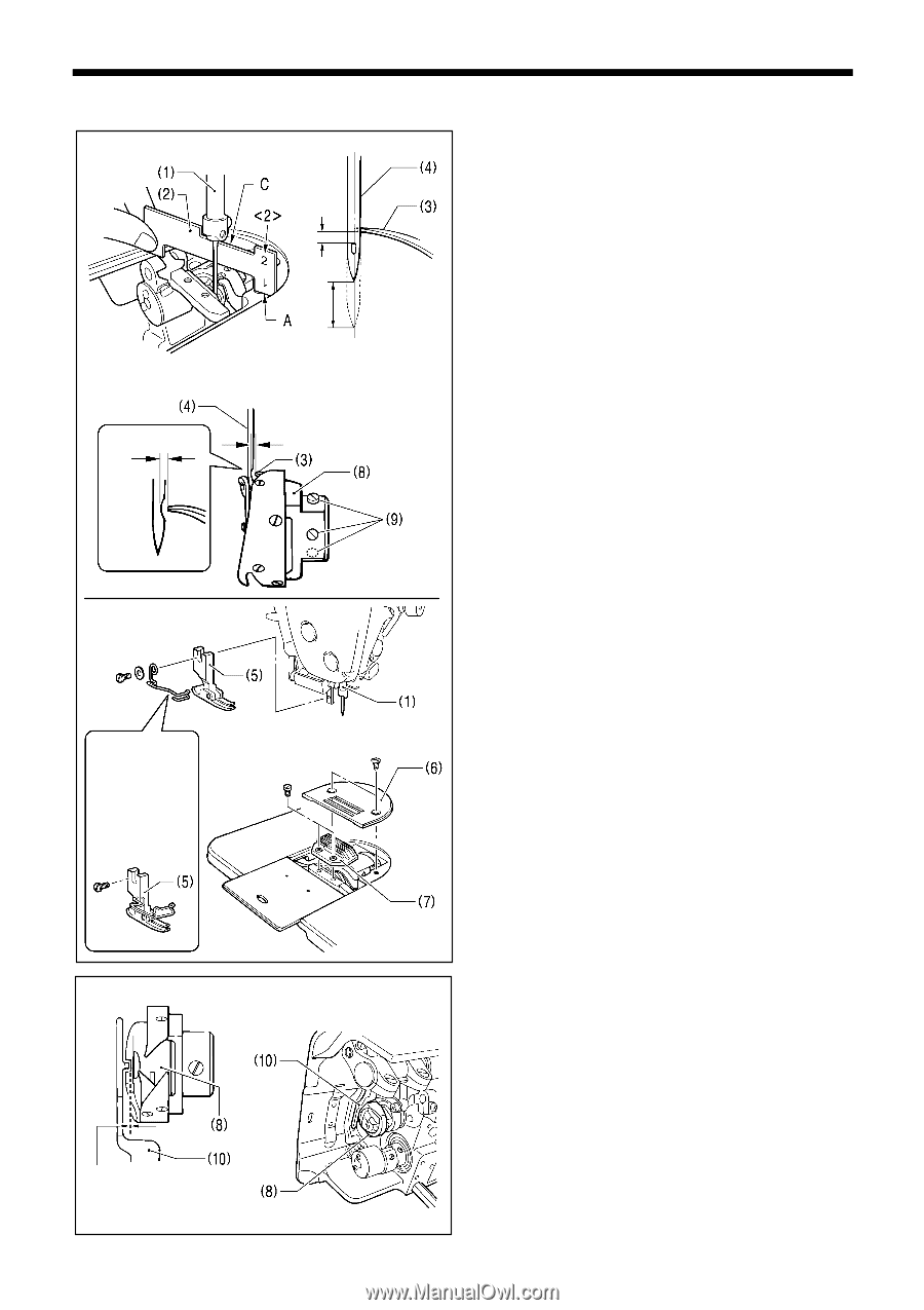
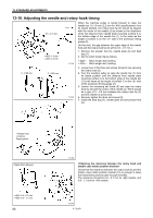
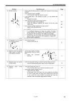
13. STANDARD ADJUSTMENTS 13-10. Adjusting the needle and rotary hook timing 0.5 - 0.7 mm 1.8 mm 2.2 mm 3775M When the machine pulley is turned forward to raise the needle bar (1) 1.8 mm (2.2 mm for -405 specifications) from its lowest position, the rotary hook tip (3) should be aligned with the center of the needle (4) as shown in the illustration when the distance from needle plate mounting surface A to the bottom edge of the needle bar (1) is the same as the height of surface C on the side of the accessory timing gauge (2). (At this time, the gap between the upper edge of the needle hole and the rotary hook tip (3) will be 0.5 - 0.7 mm.) 1. Remove the presser foot (5), needle plate (6) and feed dog (7). 2. Set the stitch length dial as follows. ... Stitch length dial 0 setting. ... Stitch length dial 3 setting. 0 - 0.05 mm 0 - 0.05 mm 3776M 3. Loosen two of the three set screws (9) which are securing the rotary hook (8). 4. Turn the machine pulley to raise the needle bar (1) from its lowest position until the distance from needle plate mounting surface A to the bottom edge of the needle bar (1) is the same as the height of surface C on the side of the accessory timing gauge (2). 5. Loosen the remaining set screw (9) and align the rotary hook tip (3) with the center of the needle (4). There should be a gap of 0 - 0.5 mm between the rotary hook tip (3) and the needle (4) at this time. 6. Securely tighten the three set screws (9). 7. Install the feed dog (7), needle plate (6) and presser foot (5). 0.4 - 0.7 mm 0.6 - 1.1 mm 55 3777M Check that the clearance between the rotary hook (8) and the bobbin case holder position bracket (10) is enough to allow the thread being used to pass through smoothly. The clearance should be 0.4 - 0.7 mm for -4[]3 models, and 0.6 - 1.1 mm for -405 models. 3778M S-7220B
-
 1
1 -
2
-
3
-
4
-
5
-
6
-
7
-
8
-
9
-
10
-
11
-
12
-
13
-
14
-
15
-
16
-
17
-
18
-
19
-
20
-
21
-
22
-
23
-
24
-
25
-
26
-
27
-
28
-
29
-
30
-
31
-
32
-
33
-
34
-
35
-
36
-
37
-
38
-
39
-
40
-
41
-
42
-
43
-
44
-
45
-
46
-
47
-
48
-
49
-
50
-
51
-
52
-
53
-
54
-
55
-
56
-
 57
57 -
 58
58 -
 59
59 -
 60
60 -
 61
61 -
 62
62 -
 63
63 -
 64
64 -
 65
65 -
 66
66 -
 67
67 -
68
-
69
-
70
-
71
-
72
-
73
-
74
 |
 |