Canon RC-IP00 Remote Camera Controller User Manual Basic - Page 21
Name of Parts, DC 12V terminal
 |
View all Canon RC-IP00 manuals
Add to My Manuals
Save this manual to your list of manuals |
Page 21 highlights
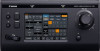
Name of Parts Front Panel F A G B C H D I E J K . A USER1 button For configuring the assigned features. B F1 knob For adjusting the assigned features. C F2 knob For adjusting the assigned features. D USER2 button For configuring the assigned features. E Zoom lever For performing the zoom operation of the remote camera. F ALARM lamp Red : Lights up when the alarm is activated. G POWER lamp Green : Lights up while the power is turned on. H Control lever For operating pan/tilt of the remote camera. I F3 knob For adjusting the assigned features. J F4 knob For adjusting the assigned features. K Operation panel Used as a touch panel. Memo : 0 For details on how to assign a function to a button or knob, please refer to the User Manual on the website. Rear Panel A B C DE F G H I J . A Power switch For turning the power on or off. B Wire Clamp For preventing the AC adapter cable from falling out. C DC 12V terminal For connecting the supplied AC adapter. D LAN terminal For connecting a LAN cable. E SERVICE terminal For use during servicing. F TALLY terminal Used for TALLY connection. G SETTING switch 1 to 4 : For switching TALLY IN and OUT. 5 to 8 : Used for servicing only. H SERIAL terminal For connecting a serial cable. Memo : 0 The specifications of the terminals are as follows. 12345678 Pin No. 1 2 3 4 Signal TX+ TXRX+ NC Pin No. 5 6 7 8 I Rating label J MAC address label Installing the Wire Clamp Signal NC RXGND GND Wire Clamp (supplied) Screw (M3) (supplied) . AC adapter (supplied) Name of Parts 21
-
 1
1 -
2
-
3
-
4
-
5
-
6
-
7
-
8
-
9
-
10
-
11
-
12
-
13
-
14
-
15
-
 16
16 -
 17
17 -
 18
18 -
 19
19 -
 20
20 -
 21
21 -
 22
22 -
 23
23 -
 24
24
 |
 |
