Cisco WS-C2950T-24 Software Guide - Page 257
Repeat Steps 2 through 4 on Switch 1 interface Fa0/2., Step 1
 |
View all Cisco WS-C2950T-24 manuals
Add to My Manuals
Save this manual to your list of manuals |
Page 257 highlights
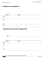
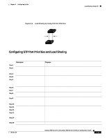
Chapter 8 Configuring VLANs Load Sharing Using STP Beginning in privileged EXEC mode, follow these steps to configure the network shown in Figure 8-6: Step 1 Step 2 Command configure terminal interface fa0/1 Step 3 switchport mode trunk Step 4 Step 5 Step 6 end show running-config Step 7 show vlan Step 8 configure terminal Step 9 interface fa0/1 Step 10 Step 11 Step 12 spanning-tree vlan 2 3 4 cost 30 end Step 13 exit Step 14 show running-config Purpose Enter global configuration mode on Switch 1. Enter interface configuration mode, and define Fa0/1 as the interface to be configured as a trunk. Configure the port as a trunk port. The trunk defaults to ISL trunking. Return to global configuration mode. Repeat Steps 2 through 4 on Switch 1 interface Fa0/2. Verify your entries. In the display, make sure that interface Fa0/1 and Fa0/2 are configured as trunk ports. When the trunk links come up, Switch 1 receives the VTP information from the other switches. Verify that Switch 1 has learned the VLAN configuration. Enter global configuration mode. Enter interface configuration mode, and define Fa0/1 as the interface to set the STP cost. Set the spanning-tree path cost to 30 for VLANs 2, 3, and 4. Return to global configuration mode. Repeat Steps 9 through 11 on Switch 1 interface Fa0/2, and set the spanning-tree path cost to 30 for VLANs 8, 9, and 10. Return to privileged EXEC mode. Verify your entries. In the display, verify that the path costs are set correctly for interface Fa0/1 and Fa0/2. 78-6511-08 Catalyst 2900 Series XL and Catalyst 3500 Series XL Software Configuration Guide 8-35
-
 1
1 -
2
-
3
-
4
-
5
-
6
-
7
-
8
-
9
-
10
-
11
-
12
-
13
-
14
-
15
-
16
-
17
-
18
-
19
-
20
-
21
-
22
-
23
-
24
-
25
-
26
-
27
-
28
-
29
-
30
-
31
-
32
-
33
-
34
-
35
-
36
-
37
-
38
-
39
-
40
-
41
-
42
-
43
-
44
-
45
-
46
-
47
-
48
-
49
-
50
-
51
-
52
-
53
-
54
-
55
-
56
-
57
-
58
-
59
-
60
-
61
-
62
-
63
-
64
-
65
-
66
-
67
-
68
-
69
-
70
-
71
-
72
-
73
-
74
-
75
-
76
-
77
-
78
-
79
-
80
-
81
-
82
-
83
-
84
-
85
-
86
-
87
-
88
-
89
-
90
-
91
-
92
-
93
-
94
-
95
-
96
-
97
-
98
-
99
-
100
-
101
-
102
-
103
-
104
-
105
-
106
-
107
-
108
-
109
-
110
-
111
-
112
-
113
-
114
-
115
-
116
-
117
-
118
-
119
-
120
-
121
-
122
-
123
-
124
-
125
-
126
-
127
-
128
-
129
-
130
-
131
-
132
-
133
-
134
-
135
-
136
-
137
-
138
-
139
-
140
-
141
-
142
-
143
-
144
-
145
-
146
-
147
-
148
-
149
-
150
-
151
-
152
-
153
-
154
-
155
-
156
-
157
-
158
-
159
-
160
-
161
-
162
-
163
-
164
-
165
-
166
-
167
-
168
-
169
-
170
-
171
-
172
-
173
-
174
-
175
-
176
-
177
-
178
-
179
-
180
-
181
-
182
-
183
-
184
-
185
-
186
-
187
-
188
-
189
-
190
-
191
-
192
-
193
-
194
-
195
-
196
-
197
-
198
-
199
-
200
-
201
-
202
-
203
-
204
-
205
-
206
-
207
-
208
-
209
-
210
-
211
-
212
-
213
-
214
-
215
-
216
-
217
-
218
-
219
-
220
-
221
-
222
-
223
-
224
-
225
-
226
-
227
-
228
-
229
-
230
-
231
-
232
-
233
-
234
-
235
-
236
-
237
-
238
-
239
-
240
-
241
-
242
-
243
-
244
-
245
-
246
-
247
-
248
-
249
-
250
-
251
-
 252
252 -
 253
253 -
 254
254 -
 255
255 -
 256
256 -
 257
257 -
 258
258 -
 259
259 -
 260
260 -
 261
261 -
 262
262 -
263
-
264
-
265
-
266
-
267
-
268
-
269
-
270
-
271
-
272
-
273
-
274
-
275
-
276
-
277
-
278
-
279
-
280
-
281
-
282
-
283
-
284
-
285
-
286
-
287
-
288
-
289
-
290
-
291
-
292
-
293
-
294
-
295
-
296
-
297
-
298
-
299
-
300
-
301
-
302
-
303
-
304
-
305
-
306
-
307
-
308
-
309
-
310
-
311
-
312
-
313
-
314
-
315
-
316
-
317
-
318
-
319
-
320
-
321
-
322
-
323
-
324
-
325
-
326
-
327
-
328
-
329
-
330
-
331
-
332
-
333
-
334
-
335
-
336
-
337
-
338
-
339
-
340
-
341
-
342
-
343
-
344
-
345
-
346
-
347
-
348
-
349
-
350
-
351
-
352
-
353
-
354
-
355
-
356
-
357
-
358
-
359
-
360
-
361
-
362
-
363
-
364
-
365
-
366
-
367
-
368
 |
 |
