Cisco WS-X4013 Hardware Maintenance Manual - Page 71
Making Single-Mode FDDI Network Connections, Connecting to an Optical Bypass Switch, See
 |
UPC - 746320976914
View all Cisco WS-X4013 manuals
Add to My Manuals
Save this manual to your list of manuals |
Page 71 highlights
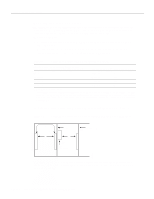
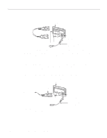
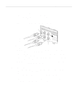
Making Network Connections Making Single-Mode FDDI Network Connections Connect a single-mode FDDI module as follows: Step 1 Connect the cable from the primary ring (from PHY-B at the primary ring upstream station) to the module's PHY-A receive port, labeled RCVR on the module panel. (See Figure 3-12.) Figure 3-12 Single-Mode Dual-Attachment FDDI Connections To primary ring From secondary ring Transmitter ports PHY-B XMTR PHY-A RCVR FDDI PRHINYG-BOP PRHINYG-AOP WARNING C1SD7AAIS0TNCEWJO: OESSALFSARYVTESOOS,TEMITCDRACEATESLRMHAXMA9SEPSLDS5SAAO,I11SEANSIE3TNAURL4IDPOKARC-LSER1EN.AER7-SIRIVI0TSSNEPUE6VERR1IMOSEDIISTBUT.CLETED S"PCueobrfmcohrpmalipeatsnecwr eJit"hStFaDndAaRrdasd, i2a1tioCnFR, H1613a To secondary ring From primary ring Receiver ports Step 2 Connect the cable to the primary ring (to PHY- A at the primary ring downstream station) to the module's PHY- B transmit port labeled XMTR. Step 3 Connect the incoming cable from the secondary ring to the module's PHY- B receive port, labeled RCVR on the module panel. Step 4 Connect the outgoing cable to the secondary ring to the module's PHY- A transmit port labeled XMTR on the module panel. Step 5 When all your network connections are complete, proceed to the section "Making Final Connections to the Router" later in this chapter. Connecting to an Optical Bypass Switch To connect the FDDI module to an external optical bypass switch (not included), use the optical bypass interface cable included with the module. Step 1 Connect one end of the optical bypass interface cable to the six-pin circular Deutsche Industrie-Norm (DIN) connector on the FDDI module panel. (See Figure 3-10 and Figure 3-11.) Step 2 Connect the other end of the optical bypass interface cable to the optical bypass switch. Proceed to the section "Making Final Connections to the Router" later in this chapter. Installing the Router 3-13
-
 1
1 -
2
-
3
-
4
-
5
-
6
-
7
-
8
-
9
-
10
-
11
-
12
-
13
-
14
-
15
-
16
-
17
-
18
-
19
-
20
-
21
-
22
-
23
-
24
-
25
-
26
-
27
-
28
-
29
-
30
-
31
-
32
-
33
-
34
-
35
-
36
-
37
-
38
-
39
-
40
-
41
-
42
-
43
-
44
-
45
-
46
-
47
-
48
-
49
-
50
-
51
-
52
-
53
-
54
-
55
-
56
-
57
-
58
-
59
-
60
-
61
-
62
-
63
-
64
-
65
-
 66
66 -
 67
67 -
 68
68 -
 69
69 -
 70
70 -
 71
71 -
 72
72 -
 73
73 -
 74
74 -
 75
75 -
 76
76 -
77
-
78
-
79
-
80
-
81
-
82
-
83
-
84
-
85
-
86
-
87
-
88
-
89
-
90
-
91
-
92
-
93
-
94
-
95
-
96
-
97
-
98
-
99
-
100
-
101
-
102
-
103
-
104
-
105
-
106
-
107
-
108
-
109
-
110
-
111
-
112
-
113
-
114
-
115
-
116
-
117
-
118
-
119
-
120
-
121
-
122
-
123
-
124
-
125
-
126
-
127
-
128
-
129
-
130
-
131
-
132
-
133
-
134
-
135
-
136
-
137
-
138
-
139
-
140
-
141
-
142
-
143
 |
 |
