Cisco WS-X4424 Hardware Maintenance Manual - Page 29
Preparing to Make Connections, Slot Numbering
 |
UPC - 746320543758
View all Cisco WS-X4424 manuals
Add to My Manuals
Save this manual to your list of manuals |
Page 29 highlights
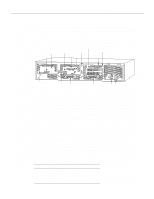
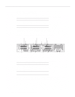
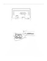
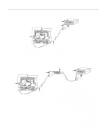
Preparing to Make Connections Preparing to Make Connections When viewed from the rear, the power cable and power switch appear on the right side of the router chassis. The system console port, auxiliary (AUX) port, and network processor module ports appear to the left of the power cable and switch. (See Figure 2-2.) Figure 2-2 Router-Rear View Showing Slot Numbering and Interface Ports Slot 3 Token Ring port 10BaseT Chassis Serial interface ports port release screw Slot 1 Ethernet port Slot 2 Dual serial module H1033a Token Ring module Ethernet module Auxiliary port Console port Power On/off switch Slot Numbering The chassis contains slots for three network processor modules. These slots correspond to the three slot numbers printed on the chassis front panel. (See Figure 1-1.) Slot numbers represent the order in which the system scans the network processor modules. Network processor module location is not slot-dependent. Any module can be moved to any other available slot location. For optimum heat dissipation, use the center slot position, slot 2, for the FDDI module if one is present. For information on how to remove and replace network processor modules, see the sections "Removing Network Processor Modules" and "Replacing Network Processor Modules" in the chapter "Maintaining and Upgrading the Router." Unit Numbering Unit numbering allows the system to distinguish between two interfaces of the same type. As viewed from the rear of the chassis, the unit numbering of the network processor modules increments from zero counting from the right to left. The system assigns unit number addresses to these network modules by starting with zero for each module interface type and numbering from right to left and from bottom to top. The lowest unit number of that interface type is the module closest to the power supply. (See Figure 2-2.) For example, the unit number addresses for the modules in Figure 2-2 are as listed in Table 2-1. Table 2-1 Slot No. 1 2 3 Unit Numbering for Dual Serial, Ethernet, and Token Ring Modules Interface Type Serial Port (Top) Serial Port (Bottom) Ethernet Token Ring Unit Address No. 1 0 0 0 Preparing for Installation 2-7
-
 1
1 -
2
-
3
-
4
-
5
-
6
-
7
-
8
-
9
-
10
-
11
-
12
-
13
-
14
-
15
-
16
-
17
-
18
-
19
-
20
-
21
-
22
-
23
-
 24
24 -
 25
25 -
 26
26 -
 27
27 -
 28
28 -
 29
29 -
 30
30 -
 31
31 -
 32
32 -
 33
33 -
 34
34 -
35
-
36
-
37
-
38
-
39
-
40
-
41
-
42
-
43
-
44
-
45
-
46
-
47
-
48
-
49
-
50
-
51
-
52
-
53
-
54
-
55
-
56
-
57
-
58
-
59
-
60
-
61
-
62
-
63
-
64
-
65
-
66
-
67
-
68
-
69
-
70
-
71
-
72
-
73
-
74
-
75
-
76
-
77
-
78
-
79
-
80
-
81
-
82
-
83
-
84
-
85
-
86
-
87
-
88
-
89
-
90
-
91
-
92
-
93
-
94
-
95
-
96
-
97
-
98
-
99
-
100
-
101
-
102
-
103
-
104
-
105
-
106
-
107
-
108
-
109
-
110
-
111
-
112
-
113
-
114
-
115
-
116
-
117
-
118
-
119
-
120
-
121
-
122
-
123
-
124
-
125
-
126
-
127
-
128
-
129
-
130
-
131
-
132
-
133
-
134
-
135
-
136
-
137
-
138
-
139
-
140
-
141
-
142
-
143
 |
 |
