Cisco WS-X4424 Hardware Maintenance Manual - Page 68
Maintaining Safe Installation Distances, i.e., line of sight.
 |
UPC - 746320543758
View all Cisco WS-X4424 manuals
Add to My Manuals
Save this manual to your list of manuals |
Page 68 highlights
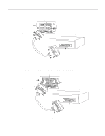
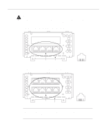
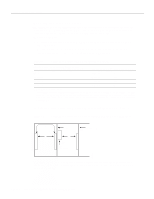
Making Network Connections Maintaining Safe Installation Distances Except at the edge connector that plugs into the host chassis expansion slot, clearance and creepage distances of X millimeters (mm) and Y mm as listed in Table 3-3 must be maintained between the cards and other parts of the host, including any other expansion cards fitted. Note that in Table 3-3: • Clearance distances are defined as the minimum distance measured in air between two points (i.e., line of sight). • Creepage distances are defined as the minimum distance measured across the surface of an insulator, between two points (i.e., following the contour of the insulator). Table 3-3 Creepage and Clearance Distances Based on Voltage Voltage Used or Generated by Other Parts of the Host or Expansion Card (Vrms or VDC)1 Creepage (Y mm)2 Clearance (X mm) Up to 50 2.4 (3.8) 2.0 Up to 125 3.0 (4.8) 2.6 Up to 250 5.0 (8.0) 4.0 Up to 300 6.4 (10.0) 4.0 1. Vrms = root mean square voltage. 2. The creepage distances not in parentheses apply when the equipment is installed in a normal office environment. The larger dimensions, in parentheses, must be applied when the equipment is installed in an environment in which dust and other types of pollution could conduct electricity because of the effects of dampness and condensation. This applies to locations subject to high humidity. Creepage and clearance distances are measured between adjacent parts as shown in Figure 3-9. Figure 3-9 y Creepage and Clearance Distances between BRI Module and Components Host Card Adjacent card x x Component H2682 Note that in Figure 3-9, X indicates the clearance distances between cards and adjacent cards and components, and Y shows the creepage path across the surface of an insulator and between the two points indicated by X. 3-10 Cisco 4000 Series Hardware Installation and Maintenance
-
 1
1 -
2
-
3
-
4
-
5
-
6
-
7
-
8
-
9
-
10
-
11
-
12
-
13
-
14
-
15
-
16
-
17
-
18
-
19
-
20
-
21
-
22
-
23
-
24
-
25
-
26
-
27
-
28
-
29
-
30
-
31
-
32
-
33
-
34
-
35
-
36
-
37
-
38
-
39
-
40
-
41
-
42
-
43
-
44
-
45
-
46
-
47
-
48
-
49
-
50
-
51
-
52
-
53
-
54
-
55
-
56
-
57
-
58
-
59
-
60
-
61
-
62
-
 63
63 -
 64
64 -
 65
65 -
 66
66 -
 67
67 -
 68
68 -
 69
69 -
 70
70 -
 71
71 -
 72
72 -
 73
73 -
74
-
75
-
76
-
77
-
78
-
79
-
80
-
81
-
82
-
83
-
84
-
85
-
86
-
87
-
88
-
89
-
90
-
91
-
92
-
93
-
94
-
95
-
96
-
97
-
98
-
99
-
100
-
101
-
102
-
103
-
104
-
105
-
106
-
107
-
108
-
109
-
110
-
111
-
112
-
113
-
114
-
115
-
116
-
117
-
118
-
119
-
120
-
121
-
122
-
123
-
124
-
125
-
126
-
127
-
128
-
129
-
130
-
131
-
132
-
133
-
134
-
135
-
136
-
137
-
138
-
139
-
140
-
141
-
142
-
143
 |
 |
