Compaq Presario A900 Compaq Presario A900 Notebook PC - Maintenance and Servic - Page 58
Display assembly, and the microphone cable
 |
View all Compaq Presario A900 manuals
Add to My Manuals
Save this manual to your list of manuals |
Page 58 highlights
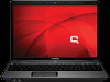
Display assembly Description Spare part number 17.0-inch, WXGA+BrightView display assembly (includes 3 WLAN antenna transceivers and cables, 462319-001 camera module and cable, microphones and cables, and logo) Before removing the display assembly, follow these steps: 1. Shut down the computer. If you are unsure whether the computer is off or in Hibernation, turn the computer on, and then shut it down through the operating system. 2. Disconnect all external devices connected to the computer. 3. Disconnect the power from the computer by first unplugging the power cord from the AC outlet and then unplugging the AC adapter from the computer. 4. Remove the battery (see Battery on page 34). 5. Disconnect the wireless antenna cables from the WLAN module (see WLAN module on page 41). 6. Remove the switch cover and keyboard (see Switch cover and keyboard on page 46). Remove the display assembly: 1. Disconnect the display panel cable (1) and the microphone cable (2) from the system board. 2. Remove the wireless antenna cables and the microphone cable from the clips (3) and routing channel. 3. Remove the four Phillips PM2.5×9.0 screws (1) that secure the display assembly to the computer. 50 Chapter 4 Removal and replacement procedures
-
 1
1 -
2
-
3
-
4
-
5
-
6
-
7
-
8
-
9
-
10
-
11
-
12
-
13
-
14
-
15
-
16
-
17
-
18
-
19
-
20
-
21
-
22
-
23
-
24
-
25
-
26
-
27
-
28
-
29
-
30
-
31
-
32
-
33
-
34
-
35
-
36
-
37
-
38
-
39
-
40
-
41
-
42
-
43
-
44
-
45
-
46
-
47
-
48
-
49
-
50
-
51
-
52
-
 53
53 -
 54
54 -
 55
55 -
 56
56 -
 57
57 -
 58
58 -
 59
59 -
 60
60 -
 61
61 -
 62
62 -
 63
63 -
64
-
65
-
66
-
67
-
68
-
69
-
70
-
71
-
72
-
73
-
74
-
75
-
76
-
77
-
78
-
79
-
80
-
81
-
82
-
83
-
84
-
85
-
86
-
87
-
88
-
89
-
90
-
91
-
92
-
93
-
94
-
95
-
96
-
97
-
98
-
99
-
100
-
101
-
102
-
103
-
104
-
105
-
106
-
107
-
108
-
109
-
110
-
111
-
112
-
113
-
114
-
115
-
116
-
117
-
118
-
119
-
120
-
121
-
122
-
123
-
124
-
125
-
126
-
127
-
128
-
129
 |
 |