Compaq Presario A900 Compaq Presario A900 Notebook PC - Maintenance and Servic - Page 70
Remove the system board, Use the optical drive connector
 |
View all Compaq Presario A900 manuals
Add to My Manuals
Save this manual to your list of manuals |
Page 70 highlights
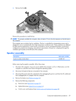
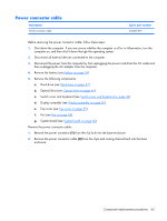
4. Disconnect the USB board cable (1) and the speaker cable (2) from the system board. 5. Remove the Phillips PM2.5×9.0 screw (1) that secures the system board to the base enclosure. 6. Flex the front edge (2) of the base enclosure outward until the audio connectors clear the openings in the base enclosure. 7. Use the optical drive connector (3) to lift the right side of the system board (4) until it rests at an angle. 8. Remove the system board (5) by sliding it up and to the right until it is clear of the base enclosure. Reverse this procedure to install the system board. 62 Chapter 4 Removal and replacement procedures
-
 1
1 -
2
-
3
-
4
-
5
-
6
-
7
-
8
-
9
-
10
-
11
-
12
-
13
-
14
-
15
-
16
-
17
-
18
-
19
-
20
-
21
-
22
-
23
-
24
-
25
-
26
-
27
-
28
-
29
-
30
-
31
-
32
-
33
-
34
-
35
-
36
-
37
-
38
-
39
-
40
-
41
-
42
-
43
-
44
-
45
-
46
-
47
-
48
-
49
-
50
-
51
-
52
-
53
-
54
-
55
-
56
-
57
-
58
-
59
-
60
-
61
-
62
-
63
-
64
-
 65
65 -
 66
66 -
 67
67 -
 68
68 -
 69
69 -
 70
70 -
 71
71 -
 72
72 -
 73
73 -
 74
74 -
 75
75 -
76
-
77
-
78
-
79
-
80
-
81
-
82
-
83
-
84
-
85
-
86
-
87
-
88
-
89
-
90
-
91
-
92
-
93
-
94
-
95
-
96
-
97
-
98
-
99
-
100
-
101
-
102
-
103
-
104
-
105
-
106
-
107
-
108
-
109
-
110
-
111
-
112
-
113
-
114
-
115
-
116
-
117
-
118
-
119
-
120
-
121
-
122
-
123
-
124
-
125
-
126
-
127
-
128
-
129
 |
 |

4
.
Disconnect the USB board cable
(1)
and the speaker cable
(2)
from the system board.
5
.
Remove the Phillips PM2.5×9.0 screw
(1)
that secures the system board to the base enclosure.
6
.
Flex the front edge
(2)
of the base enclosure outward until the audio connectors clear the openings
in the base enclosure.
7
.
Use the optical drive connector
(3)
to lift the right side of the system board
(4)
until it rests at an
angle.
8
.
Remove the system board
(5)
by sliding it up and to the right until it is clear of the base enclosure.
Reverse this procedure to install the system board.
62
Chapter
4
Removal and replacement procedures