Compaq Presario A900 Compaq Presario A900 Notebook PC - Maintenance and Servic - Page 69
Processor see, WLAN module see
 |
View all Compaq Presario A900 manuals
Add to My Manuals
Save this manual to your list of manuals |
Page 69 highlights
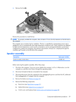
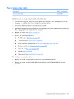
4. Remove the battery (see Battery on page 34). 5. Remove the following components: a. Hard drive (see Hard drive on page 37) b. Optical drive (see Optical drive on page 44) c. Switch cover and keyboard (see Switch cover and keyboard on page 46) d. Display assembly (see Display assembly on page 50) e. Top cover (see Top cover on page 55) f. Fan (see Fan on page 58) When replacing the system board, be sure that the following components are removed from the defective system board and installed on the replacement system board: ● Memory modules (see Memory module on page 39) ● WLAN module (see WLAN module on page 41) ● Heat sink (see Heat sink on page 69) ● Processor (see Processor on page 71) Remove the system board: 1. Turn the computer upside down, with the front toward you 2. Disconnect the power connector cable from the system board. 3. Turn the computer right-side up, with the front toward you. Component replacement procedures 61
-
 1
1 -
2
-
3
-
4
-
5
-
6
-
7
-
8
-
9
-
10
-
11
-
12
-
13
-
14
-
15
-
16
-
17
-
18
-
19
-
20
-
21
-
22
-
23
-
24
-
25
-
26
-
27
-
28
-
29
-
30
-
31
-
32
-
33
-
34
-
35
-
36
-
37
-
38
-
39
-
40
-
41
-
42
-
43
-
44
-
45
-
46
-
47
-
48
-
49
-
50
-
51
-
52
-
53
-
54
-
55
-
56
-
57
-
58
-
59
-
60
-
61
-
62
-
63
-
 64
64 -
 65
65 -
 66
66 -
 67
67 -
 68
68 -
 69
69 -
 70
70 -
 71
71 -
 72
72 -
 73
73 -
 74
74 -
75
-
76
-
77
-
78
-
79
-
80
-
81
-
82
-
83
-
84
-
85
-
86
-
87
-
88
-
89
-
90
-
91
-
92
-
93
-
94
-
95
-
96
-
97
-
98
-
99
-
100
-
101
-
102
-
103
-
104
-
105
-
106
-
107
-
108
-
109
-
110
-
111
-
112
-
113
-
114
-
115
-
116
-
117
-
118
-
119
-
120
-
121
-
122
-
123
-
124
-
125
-
126
-
127
-
128
-
129
 |
 |
