Compaq Presario CQ36-100 Compaq Presario CQ35 and CQ36 Notebook PC - Maintenan - Page 100
Keyboard cover see, one-half turn counterclockwise until
 |
View all Compaq Presario CQ36-100 manuals
Add to My Manuals
Save this manual to your list of manuals |
Page 100 highlights
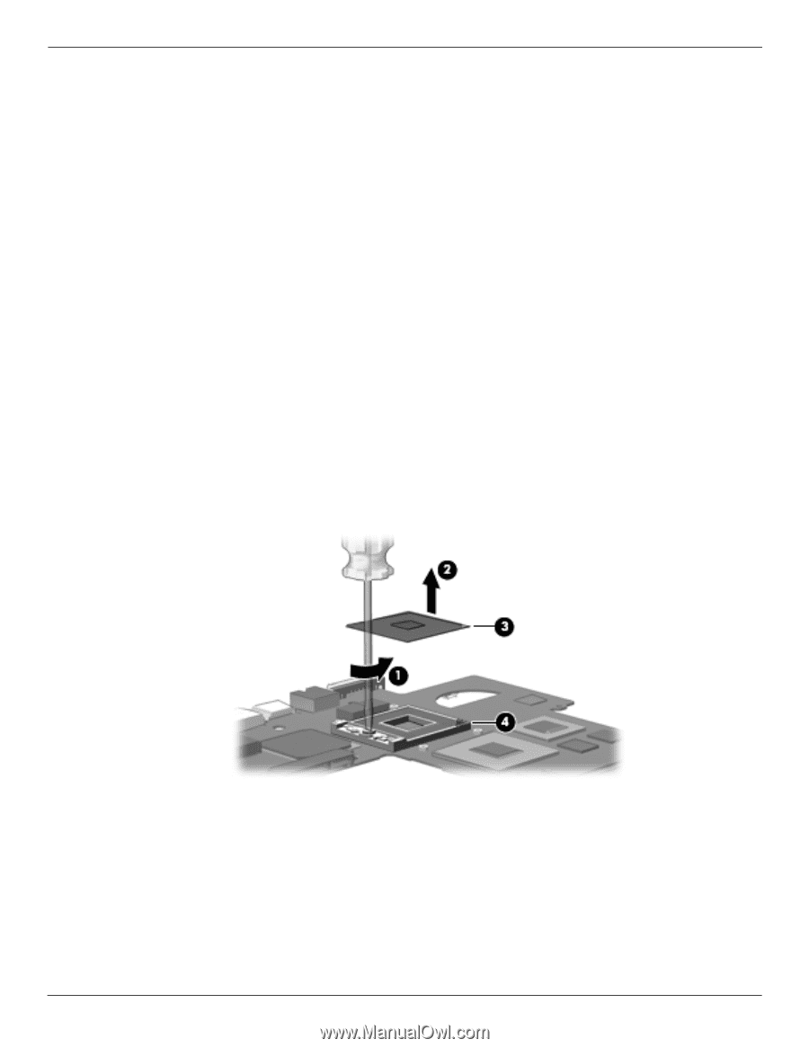
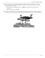
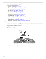
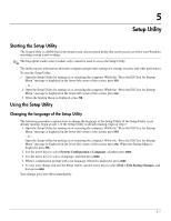
Removal and replacement procedures 4. Remove the battery (see "Battery" on page 7). 5. Remove the following components: a. Hard drive (see "Hard drive" on page 8) b. Memory module (see "Memory module" on page 11) c. WLAN module (see "WLAN module" on page 12) d. RTC battery (see "RTC battery" on page 19) e. Optical drive (see "Optical drive" on page 20) f. Keyboard (see "Keyboard" on page 22) g. Keyboard cover (see "Keyboard cover" on page 24) h. Right speaker (see "Right speaker" on page 26) i. Display assembly (see "Display assembly" on page 32). j. Top cover (see "Top cover" on page 27). k. System board (see "System board" on page 43). l. Fan/heat sink assembly (see "Fan/heat sink assembly" on page 46). Remove the processor: 1. Use a flat-bladed screwdriver to turn the processor locking screw 1 one-half turn counterclockwise until you hear a click. 2. Lift the processor 2 straight up and remove it. ✎ When you install the processor, the gold triangle 3 on the processor must be aligned with the triangle 4 embossed on the processor socket. Reverse this procedure to install the processor. 4-52
-
 1
1 -
2
-
3
-
4
-
5
-
6
-
7
-
8
-
9
-
10
-
11
-
12
-
13
-
14
-
15
-
16
-
17
-
18
-
19
-
20
-
21
-
22
-
23
-
24
-
25
-
26
-
27
-
28
-
29
-
30
-
31
-
32
-
33
-
34
-
35
-
36
-
37
-
38
-
39
-
40
-
41
-
42
-
43
-
44
-
45
-
46
-
47
-
48
-
49
-
50
-
51
-
52
-
53
-
54
-
55
-
56
-
57
-
58
-
59
-
60
-
61
-
62
-
63
-
64
-
65
-
66
-
67
-
68
-
69
-
70
-
71
-
72
-
73
-
74
-
75
-
76
-
77
-
78
-
79
-
80
-
81
-
82
-
83
-
84
-
85
-
86
-
87
-
88
-
89
-
90
-
91
-
92
-
93
-
94
-
 95
95 -
 96
96 -
 97
97 -
 98
98 -
 99
99 -
 100
100 -
 101
101 -
 102
102 -
 103
103 -
 104
104 -
 105
105 -
106
-
107
-
108
-
109
-
110
-
111
-
112
-
113
-
114
-
115
-
116
-
117
-
118
-
119
-
120
-
121
-
122
-
123
-
124
-
125
-
126
-
127
-
128
-
129
-
130
-
131
-
132
-
133
-
134
-
135
-
136
-
137
-
138
-
139
-
140
-
141
-
142
-
143
-
144
-
145
-
146
-
147
-
148
-
149
-
150
-
151
-
152
-
153
-
154
 |
 |