Compaq Presario CQ36-100 Compaq Presario CQ35 and CQ36 Notebook PC - Maintenan - Page 94
Fan/heat sink assembly, Memory module see
 |
View all Compaq Presario CQ36-100 manuals
Add to My Manuals
Save this manual to your list of manuals |
Page 94 highlights
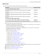
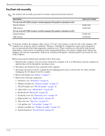
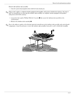
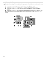
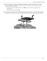
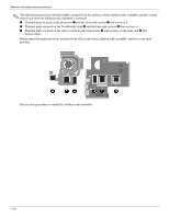
Removal and replacement procedures Fan/heat sink assembly ✎ The fan/heat sink assembly spare part kit includes replacement thermal material. Description For use only with CQ35 computer models equipped with graphics subsystems with: Discrete memory UMA memory For use only with CQ36 computer models equipped with graphics subsystems with: Discrete memory UMA memory Spare part number 531814-001 531813-001 591431-001 591430-001 ✎ To properly ventilate the computer, allow at least a 7.6-cm (3-in) clearance on the left side of the computer. The computer uses an electric fan for ventilation. The fan is controlled by a temperature sensor and is designed to turn on automatically when high temperature conditions exist. These conditions are affected by high external temperatures, system power consumption, power management/battery conservation configurations, battery fast charging, and software requirements. Exhaust air is displaced through the ventilation grill located on the left side of the computer. Before removing the fan/heat sink assembly, follow these steps: 1. Shut down the computer. If you are unsure whether the computer is off or in Hibernation, turn the computer on, and then shut it down through the operating system. 2. Disconnect all external devices connected to the computer. 3. Disconnect the power from the computer by first unplugging the power cord from the AC outlet, and then unplugging the AC adapter from the computer. 4. Remove the battery (see "Battery" on page 7). 5. Remove the following components: a. Hard drive (see "Hard drive" on page 8) b. Memory module (see "Memory module" on page 11) c. WLAN module (see "WLAN module" on page 12) d. Optical drive (see "Optical drive" on page 20) e. Keyboard (see "Keyboard" on page 22) f. Keyboard cover (see "Keyboard cover" on page 24) g. Right speaker (see "Right speaker" on page 26) h. Top cover (see "Top cover" on page 27). i. Left speaker (see "Left speaker" on page 31) j. Display assembly (see "Display assembly" on page 32). k. System board (see "System board" on page 43). 4-46
-
 1
1 -
2
-
3
-
4
-
5
-
6
-
7
-
8
-
9
-
10
-
11
-
12
-
13
-
14
-
15
-
16
-
17
-
18
-
19
-
20
-
21
-
22
-
23
-
24
-
25
-
26
-
27
-
28
-
29
-
30
-
31
-
32
-
33
-
34
-
35
-
36
-
37
-
38
-
39
-
40
-
41
-
42
-
43
-
44
-
45
-
46
-
47
-
48
-
49
-
50
-
51
-
52
-
53
-
54
-
55
-
56
-
57
-
58
-
59
-
60
-
61
-
62
-
63
-
64
-
65
-
66
-
67
-
68
-
69
-
70
-
71
-
72
-
73
-
74
-
75
-
76
-
77
-
78
-
79
-
80
-
81
-
82
-
83
-
84
-
85
-
86
-
87
-
88
-
 89
89 -
 90
90 -
 91
91 -
 92
92 -
 93
93 -
 94
94 -
 95
95 -
 96
96 -
 97
97 -
 98
98 -
 99
99 -
100
-
101
-
102
-
103
-
104
-
105
-
106
-
107
-
108
-
109
-
110
-
111
-
112
-
113
-
114
-
115
-
116
-
117
-
118
-
119
-
120
-
121
-
122
-
123
-
124
-
125
-
126
-
127
-
128
-
129
-
130
-
131
-
132
-
133
-
134
-
135
-
136
-
137
-
138
-
139
-
140
-
141
-
142
-
143
-
144
-
145
-
146
-
147
-
148
-
149
-
150
-
151
-
152
-
153
-
154
 |
 |