Compaq Presario V2000 Compaq Presario V2600 Notebook PC - Maintenance and Serv - Page 102
Remove the Mini Card module, away from the socket at an angle.
 |
View all Compaq Presario V2000 manuals
Add to My Manuals
Save this manual to your list of manuals |
Page 102 highlights
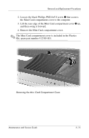
Removal and Replacement Procedures 5. Make note of which wireless antenna cable is attached to which antenna clip on the Mini Card module before disconnecting the cables, then disconnect the cables 1 from the module. 6. Remove the two black Phillips PM2.0×5.0 screws 2 that secure the Mini Card module to the system board. (The edge of the module opposite the Mini Card socket rises away from the computer). 7. Remove the Mini Card module 3 by pulling the module away from the socket at an angle. ✎ Mini Card modules are designed with a notch 4 to prevent incorrect installation into the Mini Card module socket. Removing a Mini Card Module Reverse the above procedure to install a Mini Card module. 5-16 Maintenance and Service Guide
-
 1
1 -
2
-
3
-
4
-
5
-
6
-
7
-
8
-
9
-
10
-
11
-
12
-
13
-
14
-
15
-
16
-
17
-
18
-
19
-
20
-
21
-
22
-
23
-
24
-
25
-
26
-
27
-
28
-
29
-
30
-
31
-
32
-
33
-
34
-
35
-
36
-
37
-
38
-
39
-
40
-
41
-
42
-
43
-
44
-
45
-
46
-
47
-
48
-
49
-
50
-
51
-
52
-
53
-
54
-
55
-
56
-
57
-
58
-
59
-
60
-
61
-
62
-
63
-
64
-
65
-
66
-
67
-
68
-
69
-
70
-
71
-
72
-
73
-
74
-
75
-
76
-
77
-
78
-
79
-
80
-
81
-
82
-
83
-
84
-
85
-
86
-
87
-
88
-
89
-
90
-
91
-
92
-
93
-
94
-
95
-
96
-
 97
97 -
 98
98 -
 99
99 -
 100
100 -
 101
101 -
 102
102 -
 103
103 -
 104
104 -
 105
105 -
 106
106 -
 107
107 -
108
-
109
-
110
-
111
-
112
-
113
-
114
-
115
-
116
-
117
-
118
-
119
-
120
-
121
-
122
-
123
-
124
-
125
-
126
-
127
-
128
-
129
-
130
-
131
-
132
-
133
-
134
-
135
-
136
-
137
-
138
-
139
-
140
-
141
-
142
-
143
-
144
-
145
-
146
-
147
-
148
-
149
-
150
-
151
-
152
-
153
-
154
-
155
-
156
-
157
-
158
-
159
-
160
-
161
-
162
-
163
-
164
-
165
-
166
-
167
-
168
-
169
-
170
-
171
-
172
-
173
-
174
-
175
-
176
-
177
-
178
-
179
-
180
-
181
-
182
-
183
-
184
-
185
-
186
-
187
-
188
-
189
-
190
-
191
-
192
-
193
-
194
-
195
-
196
-
197
-
198
-
199
-
200
-
201
-
202
-
203
-
204
-
205
-
206
-
207
-
208
-
209
-
210
-
211
-
212
-
213
-
214
-
215
-
216
-
217
-
218
-
219
-
220
-
221
 |
 |

5–16
Maintenance and Service Guide
Removal and Replacement Procedures
5. Make note of which wireless antenna cable is attached to
which antenna clip on the Mini Card module before
disconnecting the cables, then disconnect the cables
1
from
the module.
6. Remove the two black Phillips PM2.0×5.0 screws
2
that
secure the Mini Card module to the system board. (The edge
of the module opposite the Mini Card socket rises away from
the computer).
7. Remove the Mini Card module
3
by pulling the module
away from the socket at an angle.
✎
Mini Card modules are designed with a notch
4
to prevent
incorrect installation into the Mini Card module socket.
Removing a Mini Card Module
Reverse the above procedure to install a Mini Card module.