Craftsman 17541 Operation Manual - Page 21
Awarning
 |
View all Craftsman 17541 manuals
Add to My Manuals
Save this manual to your list of manuals |
Page 21 highlights
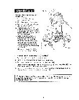
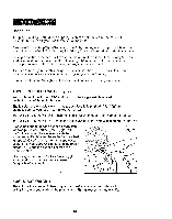
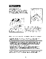
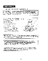
LED WORKLIGHTS (Fig. 8) Your router motor has 3 built-in worklights located around the collet/nut to provide high visibility of workpiece when cutting. These lights are always "On" when the toggle switch is in the "On "position. Fig • 8 ...... " i t + Fig. 9 "LIVE TOOL INDICATOR" LIGHT (Fig. 9) Your router also has a "LIVE TOOL INDICATOR" green light, located on the motor housing top cap where the power cord enters the motor housing, This green light is always on when router motor is plugged into power source. PLACING THE ROUTER ONTO THE WORKPIECE AND STARTING THE CUT A WARNING: Before operating your router follow all safety instructions I in this manual. Failure to do so could result in serious personal injury. I NOTE: Making test cuts is essential with most routing applications. Even with careful set-ups you won't know exactly how the cut will go until you try it out. A test cut will give you a feel for the set-up, the router's speed, the depth of cut and how the cutter bit reacts to the workpiece. Much of routing is a trial-and-error process of making various adjustments, followed by test cuts as you become familiar with all of your router's operational abilities. To avoid ruining good material, make your test cuts on scrap materials. Placing your router onto a workpiece (starting the cut) with a fixed base depends on the type of routing you are going to produce: Edge Routing or Internal Routing 21
-
 1
1 -
2
-
3
-
4
-
5
-
6
-
7
-
8
-
9
-
10
-
11
-
12
-
13
-
14
-
15
-
 16
16 -
 17
17 -
 18
18 -
 19
19 -
 20
20 -
 21
21 -
 22
22 -
 23
23 -
 24
24 -
 25
25 -
 26
26 -
27
-
28
-
29
-
30
-
31
-
32
-
33
-
34
-
35
-
36
-
37
-
38
-
39
-
40
 |
 |
