Craftsman 9-19905 Owners Manual
Craftsman 9-19905 - 1/2dr 1/4npt 500ft/lb Sq Dr Impact Wrench Manual
 |
UPC - 663023015422
View all Craftsman 9-19905 manuals
Add to My Manuals
Save this manual to your list of manuals |
Craftsman 9-19905 manual content summary:
- Craftsman 9-19905 | Owners Manual - Page 1
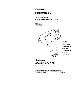
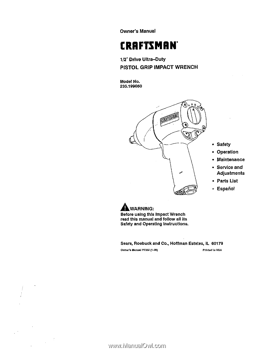
CRAFTSMIIN" 1/2" Drive Ultra-Duty PISTOL GRIP IMPACT WRENCH Model No. 235.199050 _WARNING: Before using this Impact Wrench read this manual and follow all its Safety and Operating Instructions. • Safety ° Operation ° Maintenance ° Service and Adjustments = Parts List • Espa_oi Sears, Roebuck and - Craftsman 9-19905 | Owners Manual - Page 2
the Tool Operation Air Supply and Connections Using the Power Management System Specifications Maintenance Lubrication Service and Adjustment Disassembly Assembly Troubleshooting Parts List Exploded Drawing Parts for Ordering EspaSol PAGE 2 3-5 6-7 8-15 16 17-19 20-37 FULL TWO YEAR WARRANTY If - Craftsman 9-19905 | Owners Manual - Page 3
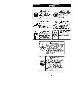
,_WARNING Always wear eye protection when operating or performing maintenance on this tool. _._l_gl_ Do not use damaged, frayed or deteriorated air hoses and fittings, _WARNING Always wear hearing protection when operating this tool. Operate at 90 psig (6.2 bar/620 kPa) Maximum air i pressure. - Craftsman 9-19905 | Owners Manual - Page 4
information which is important but not hazard related. This Craftsman Impact Wrench is designed for use in general automotive repair, tire service and heavy duty fleet applications. ,_WARNING: Important safety information enclosed. Read this manual before operating tool. It is the responsibility of - Craftsman 9-19905 | Owners Manual - Page 5
PLACING TOOL IN SERVICE (continued) • Do not remove any labels. Replace any damaged label. • The use impact wrench. • This tool is not designed for working in explosive atmospheres. ° This tool is not insulated against electric shock. NOTICE: The use of other than genuine Craftsman replacement parts - Craftsman 9-19905 | Owners Manual - Page 6
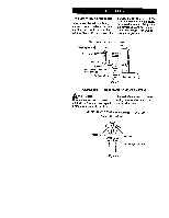
Branch line 2 times air - _ I [_ _1 I toolinletsize t = Drainregulady_ Compressor_ Figure 1 USING THE POWER MANAGEMENT SYSTEM ,_WARNING: Air wrenches are not torque controt devices. Fastenerswith specific torque requirements must be checked with suitabletorque measuringdevices after - Craftsman 9-19905 | Owners Manual - Page 7
the forward direction only. The Air Wrench will always operate at maximum power output settings. SPECIFICATIONS Model 19905 Type of Handle pistol grip Drive 1/2'" Impacts per min. oil. Craftsman 18830 Oil Craftsman 18830 Grease for routine external lubrication of the impact mechanism through - Craftsman 9-19905 | Owners Manual - Page 8
1. Clamp the handle of the impact wrench in a vise with leather- covered jaws with the square driver positioned horizontally. NOTICE: Avoid excessive clamping pressure which can damage the Housing and can cause difficulty when removing the parts. 2. Unscrew and remove the four Hammer Case Screws - Craftsman 9-19905 | Owners Manual - Page 9
NOTICE: If you continueto rotate the Anvil, it will cam the Hammers out of engagement. Don't do this; merely rotate the Anvil until it comes up solid. 3. Hold the Hammer Frame firmly and without disturbing the hammers, gently lift the Anvil while simultaneously rotating it clockwise about 1/8 of a - Craftsman 9-19905 | Owners Manual - Page 10
on inlet retainer clip (both sides) Figure 7 3. With the Inlet Bushing stillin the vise, remove the Tilt Valve Seat Retainer (31) and Tilt Valve Seat Support (30). Use a hooked tool with no sharp edges to remove the Tilt Valve Seat (29) from the Inlet Bushing. See Figure 8. Tilt valve stem - Craftsman 9-19905 | Owners Manual - Page 11
and the Bottom Reverse Valve O-ring (37) from the Reverse Valve. ASSEMBLY General Instructions 1. Whenever grasping a tool or part in a vise, always use leather-covered vise jaws to protect the surface of the part and help prevent distortion.This is particularlytrue of threaded members and housings - Craftsman 9-19905 | Owners Manual - Page 12
throughthe Hammer Case Grease Fitting(17). When disassemblingand assemblingthe impact mechanism, remove all grease from the impact mechanism and Hammer Case and lu- bricate the impact mechanism and Hammer Case Bushing (16) with Craftsman No. 18830 Grease. 3. Apply a film of o-ring lubricantto all - Craftsman 9-19905 | Owners Manual - Page 13
(25), Inlet Retainer Clip (32), inlet Bushing Seal (26), Tilt Valve Spring (32), Tilt Valve (27) Tilt Valve Seat (29) and Tilt Valve Seat Support ,_3o). WARNING: The "131Vtalve Seat Retainer (31) must be properly installed in the groove in the Inlet Bushing (22). To check for correct installation of - Craftsman 9-19905 | Owners Manual - Page 14
the Power Management Dial Seal (42) on the Power Management Dial (41) and install the Dial in the end of the Cylinder. Assembly of the Impact Mechanism ;_-_r] Tophammer notoh Bottom hammer haft-round notch on left Figure 18 14 - Craftsman 9-19905 | Owners Manual - Page 15
want to change the location of the existing Hammers to utilize both impacting surfaces, slide the Hammers in the Hammer Frame so that the half is not installed correctly, the Air Wrench will not function properly. See Figure 19. 4. Apply a thin film of Craftsman No. 18830 Grease on inside surface - Craftsman 9-19905 | Owners Manual - Page 16
Trouble Low power Motor will not run Tool will not impact Probable Cause Solution Dry Motor Daily, inject 3 cc of Craftsman No. these condi- tions exist. Replace End Plates if they are scored. Dirty motor parts. Disassemble the Tool and clean with a suitable, cleaning solution in a well - Craftsman 9-19905 | Owners Manual - Page 17
235.199050 \\ \ \ \ \ \ \ \ \ \ \ \ \\ \ \- \ \ \ 17 - Craftsman 9-19905 | Owners Manual - Page 18
PART NUMBER'-'---_ + ...& CO + + 1 C_,linder 2 Front End -A703 2131-703 2131-704 2131-724 SN2131-D727 2131-941 PART NUMBER-'--_ 17 Hammer Case Grease Fitting 18 Hammer Case Gasket ....... 23 Inlet Bushing Screen .... 5RA-61 24 Inlet Parts Kit 2131-1(303 25 Washer 26 Inlet Bushing - Craftsman 9-19905 | Owners Manual - Page 19
A329 2131-K75 . PART NUMBER--'-'_ 41 Power Management Assembly 42 Power Management Dial Seal 43 Inlet Clip Removal Tool ....... Craftsman Pneumatic Tool 2131 -A249 2131-322 Care Kit (Oil, Grease) (Available through Craftsman ® Catalog) .. 9-18830 Owner's Manual P7350 _t Hammer Kit - Craftsman 9-19905 | Owners Manual - Page 20
GARANT_ TOTALDEDOSANOS Si este producto fallara debldo a un defecto en el material de fabricacibn o la mano de obra dentro de los dos afios a partir de la fecha de adquisicl6n, Sears Io reparard o sustituird, seg_n consldere oportuno, sin cargo. Entregue el producto en un centro de servlcio Sears - Craftsman 9-19905 | Owners Manual - Page 21
AADVERTENC_ Usar siempre protencci6n ocular al manejar o realizar operaciones de mantenlmlento an esta herramlenta. _AADVERTENCIA @ Usar siempre proteccl6n para los oidos al manejar esta herramienta. No utllizar mangueras de aire y accesorios da6adoe, desgastados ni deterlorados, Manejar la - Craftsman 9-19905 | Owners Manual - Page 22
Incluir bajo el encabezamiento NOTA. Esta Ilaves de impacto Craftsman modelo 19905 est_.ndiseSadas para su utilizaci6n en reparaciones generales de automSviles la herramienta est_ al tanto de la informaci6n que contiene este manual. El hacer caso omiso de los avisos siguientes podda ocasionar - Craftsman 9-19905 | Owners Manual - Page 23
. Consulte con el m_,dico antes de volver a utilizarla. - Utilice 5nicamente los accesorios Craftsman recomendados. • Utilice 5nicamente bocas y accesorios para llaves de impacto. No Lrtilicebocas o accesorios manuales (cromados). • Las Ilaves de impacto no son Ilaves de par. Las uniones que - Craftsman 9-19905 | Owners Manual - Page 24
deber&n comprobar con un dispositivo apropiado de medici6n de par despu_s de haberlas apretado con una Ilave neum&tica, Sistema de control de potencia modelo 19905 Indicadores de ajuste de potencia Mfnima Mando de control de potencia Figura 2 24 - Craftsman 9-19905 | Owners Manual - Page 25
potencia de creciente tama_o situados en la parte posterior de la carcase sirven solamente de en todos los ajustes. Modelo 19905 ESPECIFICACIONES Tipo de empufiadura Empufiadura de 6 20W paral el motor. Acelte Craftsman N ° 18830 Grasa Craftsman N° 18830 para lubricaciTn externa _,-_ - Craftsman 9-19905 | Owners Manual - Page 26
DESMONTAJE NOTA: Los nSmeros que aparecen entre par6ntesis en las siguientes instrucciones corresponden a los nSmeros de la ilustraci6n de piezas en las p&ginas 35-37. Instrucciones generales 1. No desarme la herramienta mds de Io necesario para sustituir o reparar las piezas dar_adas. 2. AI sujetar - Craftsman 9-19905 | Owners Manual - Page 27
posterior de la carcasa. V_ase la figura 3. Mando de control de potencia 2. Saque el mando de control de potencia de la parte posterior del cilindro (1). Saque el ret_n del mando de control de potencia (42), si hay que sustituirlo. 3, Quite la placa delantera (2) del cilindro golpeando ligeramente - Craftsman 9-19905 | Owners Manual - Page 28
un banco de trabajo. Esto aflojar_, el rodamiento de modo que caiga del cilindro. V_ase la figura 5. 7. Empuje la junta del motor (7) desde la parte posterior de la carcasa para sacarla, NOTA: AI quitar la junta del motor, no utilice un destornillador ni otro objeto puntiagudo qua pueda daSar la - Craftsman 9-19905 | Owners Manual - Page 29
sobre la v&lvula inversora para que se pueda sacar _sta por la parte inferior de la empuSadura. V_ase la figura 10. Vdlvula inversora NOTA caja de mazas (15). Si no se desarm6 el mecanismo de impacto, inyecte grasa Craftsman n-°18830 a trav_s del engrasador de la caja de mazas (17), AI desarmar y - Craftsman 9-19905 | Owners Manual - Page 30
la v&lvula inversora en cualquiera de los dos sentidos hasta que salga una orejeta contra el gatillo. 6. Observe a trav_s de la carcasa desde la parte posterior. Sila lengQeta de la v&lvula inversora est& girada hacia la izquierda, instale el bot6n derecho en la carcasa. Una vez instalado uno de - Craftsman 9-19905 | Owners Manual - Page 31
J \ V ,v ,a Pane \ posterdieor y inversora sB:tn6._deord_ _L'engt]eta Figura15 NOTA: Si no se pueden instalar f_.cilmentelos botones de sentido normal e inverso, suba un poco la v&lvula inversora en el interior de la empuSadura para que quede mejor alineada con los botones. 7. Una vez - Craftsman 9-19905 | Owners Manual - Page 32
juntadel motor i!i Figura17 2. Instale el rodamiento del rotor (3) en la parte posterior del cilindro (1). 3. Instale el rotor en el cilindro y aseg6relo (14) de una capa ligera de grasa Craftsman n°-18830. 2. Revista de abundante grasa Craftsman n_ 18830 las mordazas del yunque (8). 3. Coloque - Craftsman 9-19905 | Owners Manual - Page 33
del motor. NOTA: Cerci6rese de que la secci6n plana en la parte inferior de la junta de la caja de mazas quede instalada en la no funcionar,_ bien. V_ase la figura 19. 4. Aplique una capa delgada de grasa Craftsman nQ18830 a la superficie interior del casquillo de la caja de mazas (16) y ponga - Craftsman 9-19905 | Owners Manual - Page 34
de impacto Piezas rotas o desgastadas en el mecanismo de impacto Mecanismo de impacto mal montado Solucl6n Inyecte diariamente 3 cc de aceite Craftsman N_ 18830 en la admisi6n de aire, accionando luego la herramienta para que se lubriqueel motor. Instale correctamente el suministro de aire - Craftsman 9-19905 | Owners Manual - Page 35
235.199050 \, \ \ \ \ \ \ o_ \ 0 OJ mLL o4 \\ \ \ \ / o '\ \\ =oF- \ \- \ \ \ \ \ 35 - Craftsman 9-19905 | Owners Manual - Page 36
NUMERO DE PIEZA GO O} + 1 Cilindro 2131-3A 2 Placa delantera 2131-11 3 Rodamiento de rotor (2 2131-97 4 Paquete de aletas (juego de 6 aletas) (amarillo) 2131-42A-6 5 Rotor • • • 2131-53 6 Retenedor del rodamiento trasero del rotor 2131-6 7 Junta del motor 8 Yunque ( - Craftsman 9-19905 | Owners Manual - Page 37
se ilustra. 2131-57 2131 -A93 2131 -A329 2131-K75 2131 -A249 2131-322 NUMERO DE PIEZA -'_ Utilice el kit Craftsman N_ 18830 para el cuidado de herrarnientas neum&ticas (Aceite, Grasa) (puede obtenerse a tray,s del cat&logo Craftsman Manual del propietario Kit de mazas 9-18830 P7350 2131-THK1 - Craftsman 9-19905 | Owners Manual - Page 38
NOTE: SAVE THESE INSTRUCTIONS. DO NOT DESTROY. NOTA: GUARDE ESTAS INSTRUCCIONES. NO LAS DESTRUYA. I BOO TOOL I-ILP 38 - Craftsman 9-19905 | Owners Manual - Page 39
39 - Craftsman 9-19905 | Owners Manual - Page 40
Forthe repairor replacemenpt adsyou need delivereddirectlyto yourhome Call7 am- 7 pro,7 daysa week 1-800-366-PART (1-800-366-7278) Paraordenarpeizasconentregaa domicilio- 1.-800--659-7084 For in-homemajorbrandrepairservice Call24 hoursa day,7 daysa week 1-800-4-REPAIR (1-800--.473-7247) Parapedirsan
-
 1
1 -
 2
2 -
 3
3 -
 4
4 -
 5
5 -
 6
6 -
 7
7 -
8
-
9
-
10
-
11
-
12
-
13
-
14
-
15
-
16
-
17
-
18
-
19
-
20
-
21
-
22
-
23
-
24
-
25
-
26
-
27
-
28
-
29
-
30
-
31
-
32
-
33
-
34
-
35
-
36
-
37
-
38
-
39
-
40
 |
 |
Owner's
Manual
CRAFTSMIIN"
1/2" Drive Ultra-Duty
PISTOL
GRIP
IMPACT
WRENCH
Model No.
235.199050
•
Safety
°
Operation
°
Maintenance
°
Service
and
Adjustments
=
Parts
List
•
Espa_oi
_WARNING:
Before using this Impact Wrench
read this manual and follow all its
Safety and Operating Instructions.
Sears, Roebuck and Co., Hoffman Estates, IL 60179
Owner'=
M=nual
P7360
(1-98)
Printed
In USA