Craftsman 9-19905 Owners Manual - Page 8
Grasp the Hammer Frame 12
 |
UPC - 663023015422
View all Craftsman 9-19905 manuals
Add to My Manuals
Save this manual to your list of manuals |
Page 8 highlights
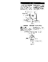
DISASSEMBLY NOTICE: Numbers in parentheses in the following instructons are part illustration numbers found on pages 17-19. General Instructions 1. Do not disassemble the tool any further than necessary to replace or repair damaged parts. 2. Whenever grasping a tool or part in a vise, always use leather-covered vise jaws to protect the surface of the part and help prevent distortion. This is particularly true of threaded members and housings. NOTICE: Always use leather-covered vise jaws when clamping the handle in a vise. Leather will conform to the shape of the handle and allow the tool to be held securely. To prevent damage to the exhaust diffuser, never clamp only the bottom of the handle. 3. Do not disassemble the tool unless you have a complete set of new gaskets and O-rings for replacement. Disassembly of the Impact Wrench 1. Clamp the handle of the impact wrench in a vise with leather- covered jaws with the square driver positioned horizontally. NOTICE: Avoid excessive clamping pressure which can damage the Housing and can cause difficulty when removing the parts. 2. Unscrew and remove the four Hammer Case Screws (11). 3. While lightly tapping on the end of the Anvil (8) with a plastic hammer, lift off the Hammer Case (15) and Hammer Case Gasket (18). NOTICE: The Front End Plate (2) might come off during the removal of the Hammer Case. Make sure that it does not drop on the floor or strike a hard or metallic surface since it might be damaged. 4. Grasp the Hammer Frame (12) and carefully lift off the entire impact mechanism, making certain not to drop the two Hammer Pins (13). Disassembly of the Impact Mechanism 1. Set the mechanism, driver end up, on the workbench. NOTICE: Note the twin hammers within the Hammer Frame. These are identical, but must be placed in the Hammer Frame in a certain relationship. Using a felt-tipped pen, mark the top "Tt" hammer and the bottom hammer "Bt" with the arrows pointing upward. Mark both Hammers on the same end. 2. With the mechanism sitting upright on the workbench, slowly rotate the Anvil in a clockwise direction until it comes up solid.
-
 1
1 -
2
-
 3
3 -
 4
4 -
 5
5 -
 6
6 -
 7
7 -
 8
8 -
 9
9 -
 10
10 -
 11
11 -
 12
12 -
 13
13 -
14
-
15
-
16
-
17
-
18
-
19
-
20
-
21
-
22
-
23
-
24
-
25
-
26
-
27
-
28
-
29
-
30
-
31
-
32
-
33
-
34
-
35
-
36
-
37
-
38
-
39
-
40
 |
 |
