Craftsman 9-19905 Owners Manual - Page 10
To remove the Rear Rotor Bear
 |
UPC - 663023015422
View all Craftsman 9-19905 manuals
Add to My Manuals
Save this manual to your list of manuals |
Page 10 highlights
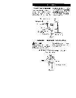
2. Pull the Trigger (33) from the front of the Housing and re- e move the Trigger O-ring (34). Rear rotor bearing SIotfortab _ Cylinder Bench with nonmetallic surface Figure 5 6. To remove the Rear Rotor Bearing, hold the Cylinder with the Rear Rotor Bearing down and tap the Cylinder on a flat, nonmetallic surface such as a work bench. This will loosen the Rear Rotor Bearing so that it will drop out of the Cylinder. See Figure 5. 7. Working from the rear of the Housing, push out the Motor Gasket (7). NOTICE: When removing the Motor Gasket, do not use a screwdriver or any other sharp object which could damage the Gasket and/or Housing. Disassembly of the Throttle Mechanism NOTICE: For ease of disassembly, we recommend using the inlet Clip Removal Tool (43). See Figure 6. Tab on inlet retainer clip (both sides) Figure 7 3. With the Inlet Bushing stillin the vise, remove the Tilt Valve Seat Retainer (31) and Tilt Valve Seat Support (30). Use a hooked tool with no sharp edges to remove the Tilt Valve Seat (29) from the Inlet Bushing. See Figure 8. Tilt valve stem Hooked tool Left-hand button Inlet bushing Inlet clip removal assembly tool Figure 6 1. Secure the Inlet Bushing in a vise. Press in both tabs of the Inlet Retainer Clip (32) and pull upward on the Housing (19). This will allow the Inlet Bushing to come free from the Handle of the Housing. See Figure 7. Figure 8 . Remove the Tilt Valve (28) and -lilt Valve Spring (27) if damaged. 5° Remove the inlet Bushing Seal (26) and Inlet Retainer Clip (32) if damaged. Remove Washer (25). NOTICE: Do not remove the Inlet Bushing Screen (23) from the Inlet Bushing unless it is damaged. Clean the Inlet Bushing Screen by using a suitable cleaning solution in a well ventilated area. 10
-
 1
1 -
2
-
3
-
4
-
 5
5 -
 6
6 -
 7
7 -
 8
8 -
 9
9 -
 10
10 -
 11
11 -
 12
12 -
 13
13 -
 14
14 -
 15
15 -
16
-
17
-
18
-
19
-
20
-
21
-
22
-
23
-
24
-
25
-
26
-
27
-
28
-
29
-
30
-
31
-
32
-
33
-
34
-
35
-
36
-
37
-
38
-
39
-
40
 |
 |
