Cub Cadet Pro Z 160L EFI Owners Manual - Page 10
Connecting the Battery Cables, Transmission Oil Expansion Reservoir, Install the Rear Hitch Bracket
 |
View all Cub Cadet Pro Z 160L EFI manuals
Add to My Manuals
Save this manual to your list of manuals |
Page 10 highlights
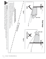
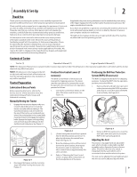
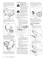
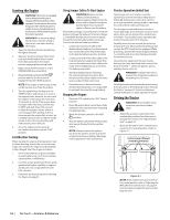
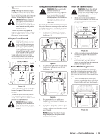
To move the seat forward or back, locate the seat adjustment rod under the seat. Push the rod to the left and slide the seat forward or back into the desired position and release the rod when the seat is in the desired position. See Figure 2-5. Figure 2-4 To adjust the arm rest, lift the arm rest and rotate the block adjustment into one of the four positions (0-3, 0 being the lowest and 3 being the highest.) and lower the arm rest. See Figure 2-6. Connecting the Battery Cables CALIFORNIA PROPOSITION 65 WARNING! Battery posts, terminals, and related accessories contain lead and lead compounds, chemicals known to the State of California to cause cancer and reproductive harm. Wash hands after handling. CAUTION: When attaching battery cables, always connect the POSITIVE (Red) wire to its terminal first, followed by the NEGATIVE (Black) wire. For shipping reasons, both battery cables on your equipment may have been left disconnected from the terminals at the factory. To connect the battery cables, proceed as follows: NOTE: The positive battery terminal is marked Pos. (+). The negative battery terminal is marked Neg. (-). NOTE: If the positive battery cable is already attached, skip ahead to step 2. 1. Remove the plastic cover, if present, from the positive battery terminal and attach the red cable to the positive battery terminal (+) with the bolt (a) and hex nut (b). See Figure 2-8. (b) (b) (a) (c) (a) Under normal operating conditions, no oil should be added to the reservoir. The COLD oil level should be no higher than approximately 1⁄4" (the "Full Cold" mark) above the bottom of the reservoir. See Figure 2-9. Figure 2-8 NOTE: Prior to the initial operation of the tractor, the oil level in the reservoir may be slightly higher than the maximum due to air in the oil lines. Operation of the tractor will eventually purge the air from the lines and the oil level will settle to the maximum. Install the Rear Hitch Bracket (If necessary) 1. Remove the hex flange screws (a) and flange lock nuts (b) that secure the hitch bracket (c) to the bumper bracket. See Figure 2-10. Figure 2-5 The mechanical suspension mechanism (if equipped) incorporates weight/ride adjustment controls for operators in the 125 to 275 lb. weight range (turn the knob on the front of the seat clockwise to increase the weight capacity and counter-clockwise to decrease. See Figure 2-7. Figure 2-6 NOTE: The seat base must be secured by the latch, otherwise, the seat assembly could tilt forward. The Operator Presence Sensor must be connected to the electrical wiring harness. 10 Section 2 - Assembly & Set-Up Figure 2-7 2. Remove the plastic cover, if present, from the negative battery terminal and attach the black cable to the negative battery terminal (-) with the bolt (a) and hex nut (b). See Figure 2-8. 3. Position the red rubber boot (c) over the positive battery terminal to help protect it from corrosion. NOTE: If the battery is put into service after the date shown on top/side of battery, charge the battery as instructed in "Charging the Battery" on page 22 prior to operating the tractor. Transmission Oil Expansion Reservoir The transmission oil expansion reservoir is connected by hoses to the RH and LH transmission assemblies, and is located behind the seat box. The function of the reservoir is to hold the natural expansion of transmission oil that occurs as the transmission warms up during operation. DO NOT FILL THE RESERVOIR. c a b a a b b Figure 2-9 2. Install the hitch bracket (c) as shown in Figure 2-11 and secure with the hex flange screws (a) and flange lock nuts (b) removed in step 1. c a b a a b b Figure 2-10
-
 1
1 -
2
-
3
-
4
-
 5
5 -
 6
6 -
 7
7 -
 8
8 -
 9
9 -
 10
10 -
 11
11 -
 12
12 -
 13
13 -
 14
14 -
 15
15 -
16
-
17
-
18
-
19
-
20
-
21
-
22
-
23
-
24
-
25
-
26
-
27
-
28
-
29
-
30
-
31
-
32
 |
 |
