Cub Cadet Pro Z 160L EFI Owners Manual - Page 11
Controls & Operation
 |
View all Cub Cadet Pro Z 160L EFI manuals
Add to My Manuals
Save this manual to your list of manuals |
Page 11 highlights
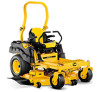
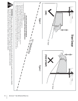
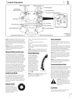
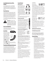
Controls & Operation LH Drive Control Lever Control Lever Adjustment Knob Cup Holder Fuel Tank Cap Fuel Level Window 3 RH Drive Control Lever Deck Lift Handle Deck Height Index Control Lever Adjustment Knob Control Panel (c)* Fuel Valve Fuel Tank Cap (b) (d) (e)+ (f)+ (a) (g)+ Fuel Level Window LH Transmission Bypass Rod RH Transmission Bypass Rod * - If Equipped + - Optional NOTE: This Operator's Manual covers several models. Tractor features may vary by model. Not all features in this manual are applicable to all tractor models and the tractor depicted may differ from yours. NOTE: References to LEFT, RIGHT, FRONT, and REAR indicate that position on the tractor when facing forward while seated in the operator's seat. RH and LH Drive Control Levers The RH and LH control levers are located on each side of the operator's seat. These hinged levers pivot outward to open space to permit the operator to either sit in the tractor seat, or to dismount the tractor. The levers must be fully opened out and in the neutral position to start the tractor engine. When the levers are fully outward, the parking brake is also engaged. Each lever controls the respective RH or LH transmission. Consequently, these levers control all of the movements of the tractor. Driving and steering utilizing these control levers is quite different from conventional tractors, and will take some practice to master. Refer to Operation for instructions on using the control levers. Control Lever Knobs The control lever knobs are located near the base of RH and LH control levers. The knobs allow the levers to be adjusted forward or rearward. Refer to Maintenance & Adjustments section for instructions on using the control levers knobs. T Ignition Switch The ignition switch is located on the RH console to the rear of the throttle or throttle/choke control lever. The ignition switch has three positions as follows: O FF ON STAR STOP - The engine and electrical system are turned off. ON - The tractor electrical system is energized. START - The starter motor will turn over the engine. Release the key immediately when the engine starts NOTE: To prevent accidental starting and/or battery discharge, remove the key from the ignition switch when the tractor is not in use. Deck Height Index The deck height index consists of several holes located on the front of the RH console. Each hole corresponds to a 1⁄4" change in the deck height position ranging from 1" at the lowest notch to 5" at the highest notch. The highest notch is also the transport position and the lowest position is the deck removal/installation position . 5" 4.5 4 3.5 3 2.5 2 1.5 1" NOTE: Do not cut grass in the deck removal/ installation position . Doing so is detrimental to the belt life. Deck Lift Handle The deck lift handle is located on the front of the RH console, and is used to raise and lower the mower deck. Depress the button on the end of the handle and push downward to lower the deck, or pull upward to raise the deck. When the desired height is attained, secure the pin in the desired index hole and release the button on the handle. NOTE: Make certain the deck is secured and the pin is fully inserted into the deck height index. The pin is keyed to help keep it in place and fits into the slotted holes on the deck height index. NOTE: The deck lift handle must always be above the pin, never hang the deck lift handle from the pin when mowing. Transmission Bypass Rods The transmission bypass rods (one for each the RH and LH transmission) are located on the rear of the tractor, just inside each rear wheel. When engaged and the lapbars fully inward in the neutral position disengaging the oparking brake, the two rods open a bypass within the hydrostatic transmissions, which allows the tractor to be pushed short distances by hand. Refer to the Assembly & Set-Up section for instructions on using the bypass feature. CAUTION: Never tow your tractor. Towing the tractor with the rear wheels on the ground may cause severe damage to the transmissions. Cup Holder The cup holder is located to the left of the operator's seat on the LH console. 11
-
 1
1 -
2
-
3
-
4
-
5
-
 6
6 -
 7
7 -
 8
8 -
 9
9 -
 10
10 -
 11
11 -
 12
12 -
 13
13 -
 14
14 -
 15
15 -
 16
16 -
17
-
18
-
19
-
20
-
21
-
22
-
23
-
24
-
25
-
26
-
27
-
28
-
29
-
30
-
31
-
32
 |
 |
