Cub Cadet Pro Z 160L EFI Owners Manual - Page 21
Deck Leveling, Adjusting the Front Gauge Wheels
 |
View all Cub Cadet Pro Z 160L EFI manuals
Add to My Manuals
Save this manual to your list of manuals |
Page 21 highlights
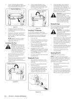
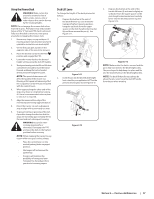
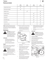
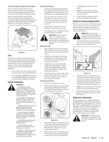
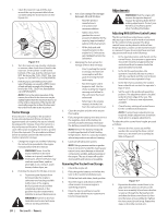
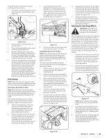
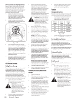
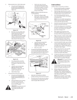
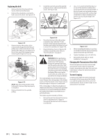
To adjust the drive control levers forward/ rearward, proceed as follows: 1. Loosen the control lever knob (a) on the side of the drive control lever (b). See Figure 4-8. 3. Loosen the lower nut (a) on the adjustable lift link (b) attached to the deck lift arm (c) to lower the deck and tighten the upper nut (d) to secure the deck in place, loosen the upper nut (d) then tighten the lower nut (a) to secure the deck in place. See Figure 4-9. (b) (d) (c) (b) (d) (c) (a) (a) Figure 4-8 2. Place the drive control lever (b) in the desired position. 3. Secure in place by tightening the control lever knob (a). See Figure 4-8. 4. Note the relative position of the drive control lever (b) to the pivot bracketnear the seat, then repeat the previous steps to reposition the other drive control lever in approximately the same position. 5. A fine-tuning adjustment can be made if the drive control levers (b) are not lining up correctly. Be certain that the control lever knob (a) is secure and loosen the two bolts securing the control lever adjuster (c) to the lower arm assembly (d). Pivot the control lever adjuster (c) forward or rearward to align the drive control levers (b). When the drive control levers (b) are aligned, re-tighten the bolts to secure the drive control lever (b). Deck Leveling NOTE: Check the tractor's tire pressure before performing any deck leveling adjustments. Refer to Tires for information regarding tire pressure. Leveling the Deck (Side-to-Side) NOTE: Check the tractor's tire pressure before performing any deck leveling adjustments. Refer to Tires for information regarding tire pressure. Always level the deck side-to-side before front to rear. If the cutting deck appears to be mowing unevenly, a side-to-side adjustment can be performed. Adjust if necessary as follows: 1. With the tractor parked on a firm, level surface, place the deck lift handle in a middle mowing position and rotate both outside blades so that they are perpendicular with the tractor. 2. Measure the distance from the outside of the left blade tip to the ground and the distance from the outside of the right blade tip to the ground. Both measurements taken should be equal. If they're not, proceed to the next step. Figure 4-9 4. The deck is properly leveled when both blade tip measurements are equal. Leveling the Deck (Front-To-Rear) NOTE: Check the tractor's tire pressure before performing any deck leveling adjustments. Refer to Tires for information regarding tire pressure. Always level the deck side-to-side before front to rear. The front of the deck should be between 1⁄4-3⁄8" lower than the rear of the deck. Adjust if necessary as follows: 1. Park the tractor on a firm, level surface and place the deck lift handle in a middle position. 2. Rotate the blade nearest the discharge chute so that it is parallel with the tractor. 3. Measure the distance from the front of the blade tip to the ground and the rear of the blade tip to the ground. The first measurement taken should be between 1⁄4" and 3⁄8" less than the second measurement. 4. Determine the approximate distance necessary for proper adjustment and proceed, if necessary. 5. Using a wrench, raise the front of deck by loosening the lock nuts to the front of the pivot pin (a) and then tighten the jam nuts on the back of the pivot pin (a) to raise the front of the deck and secure in place. See Figure 4-10. (a) (a) 6. Using a wrench, lower the front of deck by loosening the jam nuts on the back of the pivot pin (a) and then tighten the lock nut on the front of the pivot pin (a) to lower the front of the deck and secure in place. See Figure 4-10. 7. The deck is properly leveled when the front tip of the blade is 1⁄4" lower than the rear tip. Retighten the hex bolt on the left rear deck hanger links when proper adjustment is achieved. Adjusting the Front Gauge Wheels WARNING!: Keep hands and feet away from the discharge opening of the cutting deck. The front gauge wheels on the mower deck are an anti-scalp feature, and should not ride on the ground. The front gauge wheels should be approximately 1⁄4-1⁄2" above the ground when the deck is set in the desired height setting. Using the deck lift handle, set the deck in the desired height setting, then check the gauge wheel distance from the ground below. If necessary adjust the front gauge wheels as follows: 1. Visually check the distance between the front gauge wheels and the ground. If the gauge wheels are near or touching the ground, they should be raised. If more than 1⁄2" above the ground, they should be lowered. 2. Remove the lock nut (a) securing one of the front gauge wheel (b) to the deck. Remove the front gauge wheel (b), hex screw (c) and spacer (d). See Figure 4-11. (b) (a) (d) (e) (c) Figure 4-11 NOTE: There are a pair of front gauge wheels on the nose of the 54" and 60" decks. 3. Insert the hex screw (c) into the one of three index holes in the front gauge wheel bracket (e) that will give the front gauge wheel (b) a 1⁄4-1⁄2" clearance with the ground. 4. Note the index hole of the just adjusted front auge wheel (b), and adjust the other front gauge wheel (b) into the respective index hole of the other front gauge wheel bracket (e). Figure 4-10 Section 4 - Service 21
-
 1
1 -
2
-
3
-
4
-
5
-
6
-
7
-
8
-
9
-
10
-
11
-
12
-
13
-
14
-
15
-
 16
16 -
 17
17 -
 18
18 -
 19
19 -
 20
20 -
 21
21 -
 22
22 -
 23
23 -
 24
24 -
 25
25 -
 26
26 -
27
-
28
-
29
-
30
-
31
-
32
 |
 |
