Cub Cadet TANK LZ 54 TANK LZ 48 Operator's Manual - Page 31
Deck Wheels, Brakes
 |
View all Cub Cadet TANK LZ 54 manuals
Add to My Manuals
Save this manual to your list of manuals |
Page 31 highlights
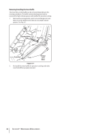
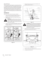
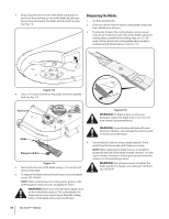
To lessen the tension on the belt loosen the flange lock nuts on the deck rods and then loosen the jam nuts until a ten-pound pull with a spring scale deflects the belt about 1⁄2". Then retighten the flange lock nuts. See Fig. 6-8. Deck Wheels WARNING! Keep hands and feet away from the discharge opening of the cutting deck. NOTE: The deck wheels are an anti-scalp feature of the deck and are not designed to support the weight of the cutting deck. The mower deck cutting height can be set using the tractor's deck lift pedal. The deck heights range from 1" to 5". The deck gauge wheel position should be approximately 1⁄4 to 1⁄2" above the ground when the deck is set in the desired height setting. Using the lift pedal, set the deck in the desired height setting, then check the gauge wheel distance from the ground below. If necessary, adjust as follows: 1. Visually check the distance between the front gauge wheels and the ground. If the gauge wheels are near or touching the ground, they should be raised. If more than 1⁄2" above the ground, they should be lowered. 2. Remove the flange lock nut and carriage bolt securing the front deck wheel and spacer to the deck. Remove the wheel and carriage bolt. Refer to Fig. 6-5. Flange Lock Nut Brakes The parking brake handle should engage with moderate force. The brake cable should not require adjustment, but if necessary proceed as follows: 1. Flip up the seat and secure in place with the seat prop. Remove the battery as instructed in the Service section. NOTE: There is a cable for each of the transmissions, be sure to adjust both cables. 2. Adjust the cable housing nuts one full turn and check parking capacity. Repeat if parking brake does not hold. See Fig. 6-6. Handbrake Bracket Cable Housing Nut Left Transmission Right Transmission Figure 6-6 NOTE: To adjust the right transmission cable, it is recommended that you remove the left transmission cable by loosening it until Z-fitting can be removed from the handbrake bracket. After adjusting the right brake cable, re-install the left brake cable and adjust as necessary. Carriage Bolt Spacer Deck Wheel Figure 6-5 3. Determine which index hole will give the deck wheel a 1⁄4" to 1⁄2" clearance with the ground. 4. Insert the carriage bolt through the appropriate index hole in the deck wheel bracket, through the spacer, the deck wheel and out the other side of the bracket. 5. Note the index hole of the just adjusted wheel, and adjust the other deck wheel to the same height as instructed in step 3. Section 6 - Maintenance & Adjustments 31
-
 1
1 -
2
-
3
-
4
-
5
-
6
-
7
-
8
-
9
-
10
-
11
-
12
-
13
-
14
-
15
-
16
-
17
-
18
-
19
-
20
-
21
-
22
-
23
-
24
-
25
-
 26
26 -
 27
27 -
 28
28 -
 29
29 -
 30
30 -
 31
31 -
 32
32 -
 33
33 -
 34
34 -
 35
35 -
 36
36 -
37
-
38
-
39
-
40
-
41
-
42
-
43
-
44
 |
 |
