D-Link DG-104SH Product Manual
D-Link DG-104SH Manual
 |
View all D-Link DG-104SH manuals
Add to My Manuals
Save this manual to your list of manuals |
D-Link DG-104SH manual content summary:
- D-Link DG-104SH | Product Manual - Page 1
D-Link DG-104SH VoIP Station Gateway Manual Version 1.10 Building Networks for People - D-Link DG-104SH | Product Manual - Page 2
Contents Package Contents 3 Introduction 4 Features and Benefits 5 Getting Started 6 Understanding Indicators 9 Configuration 11 Using the Boot Menu 21 Using Web-Based Management 30 Command Line Interface 68 Technical Specifications 76 Waranty 79 Registration 82 Contacting Technical - D-Link DG-104SH | Product Manual - Page 3
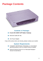
Package Contents Contents of Package: „ D-Link DG-104SH VoIP Station Gateway „ Ethernet Cable (RJ-45) „ A/C Power Adapter If any of the above items are missing, please contact your reseller. System Requirements: „ Computers with - D-Link DG-104SH | Product Manual - Page 4
to create a home or small office LAN network. Enabling NAT on the DG-104SH will allow multiple clients to connect to the Internet. It can be configured/monitored via the Console, Web browser, or Telnet and SNMP management is also supported. By routing calls over the Internet or any IP network, this - D-Link DG-104SH | Product Manual - Page 5
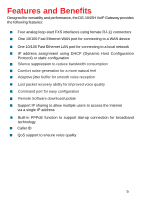
and Benefits Designed for versatility and performance, the DG-104SH VoIP Gateway provides the following features: „ Four improved voice quality „ Command port for easy configuration „ Remote Software download/update „ Support IP sharing to allow multiple users to access the Internet via a single IP - D-Link DG-104SH | Product Manual - Page 6
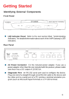
Getting Started Identifying External Components Front Panel DG-104SH „ LED Indicator Panel: Refer to the next section titled has a DC output of 12VDC/1A. „ Diagnostic Port: An RS-232 serial port used to configure the device. Plug one end of a straight-through wired RS-232 cable to the device and the - D-Link DG-104SH | Product Manual - Page 7
. „ Visually inspect the power cord and see that it is secured to the AC power connector. „ Do not place heavy objects on the DG-104SH at any time. Placing the DG-104SH in a well ventilated area is very important. Not doing so may cause damage to the unit. When installing the unit on a desktop - D-Link DG-104SH | Product Manual - Page 8
requires a straight-through cable when connecting to a computer. Make sure that your IP address on your Ethernet card is in the same subnet as the DG-104SH, otherwise it will not connect. Connecting the VoIP Gateway to a Hub/Switch When connecting the LAN port to a Hub/Switch you will need to use - D-Link DG-104SH | Product Manual - Page 9
Before configuring your VoIP Gateway, take a few minutes to look over this section and familiarize yourself with the front panel LED indicators depicted below. „ Power: This LED is lit when the device is receiving power; otherwise, it is unlit. „ Test: This LED will flash quickly when the DG-104SH - D-Link DG-104SH | Product Manual - Page 10
use. „ Phone 1 to 4: Lights when standard phone port is in use. Note: If a powered-up device is connected to a port and the port's Link/Act status indicator is unlit, the most probable cause is a cabling or connection problem (for example, wrong cable type or bad contact) or a device malfunction. 10 - D-Link DG-104SH | Product Manual - Page 11
the VoIP Gateway There are two ways to configure the VoIP gateway: „ Using a terminal or computer running the browser is referred to as the management station. Configuring the VoIP Gateway Using a Console Setting up a Console First-time configuration can be carried out through a "console," that is - D-Link DG-104SH | Product Manual - Page 12
Once you have set an IP address for your device, you can use a Telnet program (in a VT-100 compatible terminal mode) to access and configure it. Most of the screens are identical, whether accessed from the console port or from a Telnet interface. Console Usage Conventions The console interface uses - D-Link DG-104SH | Product Manual - Page 13
VoIP Gateway First make the console connection to the device and then power it on. If your terminal (or terminal emulation program) is properly configured according to the specifications defined above, you will see the POST test and the boot up process. During this process, press to reach - D-Link DG-104SH | Product Manual - Page 14
Gatekeeper mode „ Gatekeeper IP -The Gatekeeper IP address is necessary if you chose the item within the Gatekeeper Mode All of these settings are found in the first menu item in the Boot Menu named IP Configuration. Configure IP Use the key to highlight the first menu item - D-Link DG-104SH | Product Manual - Page 15
Configuration Configuring the VoIP Gateway No Gatekeeper: When No Gatekeeper is selected, the VoIP gateway will not need Gatekeeper. Auto Discovery: When Auto Discovery is selected, the VoIP gateway will auto-search the Gatekeeper from your LAN or WAN. Manual Discovery: When Manual Discovery is - D-Link DG-104SH | Product Manual - Page 16
Configuration Configuring the VoIP Gateway The VoIP gateway comes with a default IP address of 10.1.10.4. You must make sure your computer is in the same subnet - D-Link DG-104SH | Product Manual - Page 17
Configuration Configuring the VoIP Gateway Click on the Login to the web-based management module button in the middle of the window. The following window will be - D-Link DG-104SH | Product Manual - Page 18
Configuration Configuring the VoIP Gateway To begin configuring the device, click on the Config IP folder on the left-hand side of the window (shown below). Next, click on Config Device IP Address. The following window will appear: Configure Device IP Address window 18 - D-Link DG-104SH | Product Manual - Page 19
Configuration Configuring the VoIP Gateway The items on this window are described below: Restart Settings „ Get IP From: Select the method the VoIP gateway will use to obtain its IP settings once it is rebooted. Choices include: Manual: When Manual is selected, the VoIP gateway will obtain its IP - D-Link DG-104SH | Product Manual - Page 20
Configuration Configuring the VoIP Gateway Configure Gatekeeper window The items on this window are described below: „ Mode: Select the Gatekeeper mode.(Default is Auto) „ Gatekeeper IP Address: This IP address is necessary if you chose the Manual mode defined as above. „ Send Register/Unregister to - D-Link DG-104SH | Product Manual - Page 21
with a 9-socket D-shell connector and DCE-type wiring) and the appropriate cabling for the connection is being used. Please see the previous section, "Configuration," for additional information. Next, power the device on by simply plugging it in. You will see the POST test and the boot up process - D-Link DG-104SH | Product Manual - Page 22
Boot Menu, Configure IP, and press . The IP Configuration screen will be displayed: Boot Menu-IP Configuration screen Each item on the IP Configuration screen is -search the Gatekeeper from your LAN or WAN. Manual Discovery: When Manual Discovery is selected, the VoIP gateway will attempt to - D-Link DG-104SH | Product Manual - Page 23
Using the Boot Menu Configuring the IP BOOTP: When BOOTP is selected, the VoIP gateway will attempt to obtain its IP item and press for the changes to take effect. Your VoIP is now configured for use. Configuring the SNMP This screen allows you to set an SNMP trap manager. Boot Menu-SNMP - D-Link DG-104SH | Product Manual - Page 24
SNMP Configuration screen is described below: „ SNMP AuthTrap: Enables or disables the SNMP trap function „ Community: Enter the community name of the trap manager. „ IP: Enter the IP address of the trap manager. Device Information This screen displays various types of information about the DG-104SH - D-Link DG-104SH | Product Manual - Page 25
physical location of the device. „ System Contact: This is user-defined contact information for the person or department responsible for the maintenance of this device. Update Firmware and Configuration Files New software can be downloaded from a TFTP server. Use the arrow keys to highlight the - D-Link DG-104SH | Product Manual - Page 26
DEVICE TO START UPDATE to initiate the update sequence. Each item on the Update Firmware and Configuration Files screen is described below: „ Software Update Mode: This specifies downloading the image file through a WAN Link. „ TFTP Server Address: The IP address of the TFTP server where the runtime - D-Link DG-104SH | Product Manual - Page 27
Using the Boot Menu Update Firmware and Configuration Files „ File Name: The complete path and filename on the TFTP server for the desired configuration file. „ Last TFTP Server Address: This is a read-only field that displays the IP address of the last TFTP server to be accessed. Save Changes - D-Link DG-104SH | Product Manual - Page 28
the Boot Menu Factory Reset Note: After performing the Factory Reset, make sure to redefine the IP settings for the device in the IP Configuration menu. Then perform a Restart System on the device. After these three procedures are performed, your Factory Reset is complete. To perform a Factory Reset - D-Link DG-104SH | Product Manual - Page 29
Using the Boot Menu Restart System Boot Menu-Restart System screen 29 - D-Link DG-104SH | Product Manual - Page 30
DG-104SH VoIP gateway offers an embedded Web-based (hypertext) interface allowing users shots (pictures) in this guide. Note: This Web-based Management manually through a console. See the Configuring the VoIP Gateway using a Web Browser section of the "Configuration" section for specific instructions - D-Link DG-104SH | Product Manual - Page 31
and Static IP Assignment), NAT Configuration (NAT Configuration and Local Server Configuration), SNMP Trap Configuration, Administration Management, Monitor (Ethernet Statistics, DSP Statistics, Tcid Configuration, and Coding Profile), Firmware and Configuration Update, Save Changes, Factory Reset - D-Link DG-104SH | Product Manual - Page 32
Using Web-Based Management Configure Device IP Address BOOTP: When BOOTP is selected, the Click on the Save button at the bottom right of the window to save the settings. Configure Gatekeeper Configure Gatekeep window The items on this window are described below: „ Mode: Choose the Gatekeeper mode - D-Link DG-104SH | Product Manual - Page 33
Using Web-Based Management Configure Gatekeeper „ Send Register/Unregister to Gatekeeper: Determines whether „ Boot PROM Version: This displays the version number of the device's startup code. „ Firmware Version: This displays the version number of the device's runtime code. „ Hardware Revision This - D-Link DG-104SH | Product Manual - Page 34
. „ Serial Number: This field is for a user-determined identification number. „ System Name: This is a user-defined name for this device. „ System Location: This is a user-defined physical location of the device. „ System Contact: This is - D-Link DG-104SH | Product Manual - Page 35
Using Web-Based Management Prefer Codec Table Prefer Codec Table window This window allows you to view the Prefer Codec Table settings. Click the number of Tcid column on the window above to access the second Prefer Codec Table window: 35 - D-Link DG-104SH | Product Manual - Page 36
items on this window are described below: „ Tcid: This displays the port number of this device. (0: port1, 1: port2, 2: port3, 3: port4) „ Prefer Codec Type: This is a user-defined prefer codec type for the port shown as above. Click on the Save button at the bottom right of the window to save the - D-Link DG-104SH | Product Manual - Page 37
Using Web-Based Management Analog Port (Ingress Calls and Dialing Rule Settings for the Gateway's Voice Ports) First Analog Port Phone No. Table window This window allows you to view the Analog Port Telephone No. Table settings. Click the number of Tcid column on the window above to access the - D-Link DG-104SH | Product Manual - Page 38
-defined Caller ID number for the port shown as above. „ Caller ID Name: This is a user-defined Caller ID name. „ Private Type: Determines whether or not the user would like to block/ unblock the Caller ID number and Caller ID name. „ Call Forward: Toggle to Enabled to use the Call Forward function - D-Link DG-104SH | Product Manual - Page 39
Using Web-Based Management Analog Port „ Process Type: This is a user-defined which situation will activate Call Forward function. The entry is used only if the Call Forward is set to Enable. Click on the Save - D-Link DG-104SH | Product Manual - Page 40
Data Port Second Data Port Telephone No. Table window The items on this window are described below: „ Prefix Strip Telephone No.: This is a user-defined prefix strip number for outgoing calls to another device. „ Destination IP Address: Enter the IP address of the destination you would like to call - D-Link DG-104SH | Product Manual - Page 41
ATPM Mode window The items on this window are described below: „ TSGM: This Mode allow user to setup advanced ingress calls and dialing rule settings for the gateway's voice ports. „ HSMU: This Mode allow user to setup advanced egress calls and dialing rule settings. Choose the TSGM or HSMU Mode - D-Link DG-104SH | Product Manual - Page 42
Table window The items on this window are described below: „ Destination ID.: This is a user-defined destination ID for the port shown below. The ID cannot be duplicated. „ Tcid: This is a user-defined port number of this device. (0: port1, 1: port2, 2: port3, 3: port4) Enter the desired information - D-Link DG-104SH | Product Manual - Page 43
Using Web-Based Management ATPM Wizard ATPM Hunt Group Table window The items on this window are described below: „ Hunt Group.: This is a user-defined hunt group number for the destination ID shown below. „ Destination ID.: This displays the destination ID set in the last previous page. Enter the - D-Link DG-104SH | Product Manual - Page 44
This displays the Hunt Group ID set in the previous page. „ Min Digits: This is a user-defined min digits of the dial number. „ Max Digits: This is a user-defined max digits of the dial number. „ Prefix Strip: This is a user-defined prefix stripped digits of the dial number. „ Prefix Digit: This is - D-Link DG-104SH | Product Manual - Page 45
Using Web-Based Management ATPM Address Table First ATPM Address Table window This window allows you to view the ATPM Address Table settings. Click the Add icon on the window above to access the Second ATPM Address Table window: 45 - D-Link DG-104SH | Product Manual - Page 46
Using Web-Based Management ATPM Address Table Second ATPM Address Table window Enter the desired information on the window above and then click Save. 46 - D-Link DG-104SH | Product Manual - Page 47
Using Web-Based Management ATPM Hunt Group Table First ATPM Hunt Group Table window This window allows you to view the ATPM Hunt Group Table settings. Click the Add or Delete icon on the window above to access the Second ATPM Hunt Group Table window: 47 - D-Link DG-104SH | Product Manual - Page 48
Using Web-Based Management ATPM Hunt Group Table Second ATPM Hunt Group Table window Enter the desired information on the window above and then click Save. 48 - D-Link DG-104SH | Product Manual - Page 49
Using Web-Based Management ATPM Destination Table First ATPM Destination Table window This window allows you to view the ATPM Destination Table settings. Click the Add or Delete icon on the window above to access the Second ATPM Destination Table window: 49 - D-Link DG-104SH | Product Manual - Page 50
Using Web-Based Management ATPM Destination Table Second ATPM Destination Table window Enter the desired information on the window above and then click Save. 50 - D-Link DG-104SH | Product Manual - Page 51
Using Web-Based Management Dynamic IP Assignment Dynamic IP Assignment window Enter the desired information on the window above and then click Save. 51 - D-Link DG-104SH | Product Manual - Page 52
Using Web-Based Management Static IP Assignment First Static IP Assignment window Click the pointer icon on the window above to access the second Static IP Assignment window: 52 - D-Link DG-104SH | Product Manual - Page 53
Using Web-Based Management Static IP Assignment Second Static IP Assignment window Enter the desired information on the window above and then click Save. 53 - D-Link DG-104SH | Product Manual - Page 54
Using Web-Based Management NAT Configuration NAT Configuration window After entering the desired information into the window above, enable or disable the NAT Function and then click Save. 54 - D-Link DG-104SH | Product Manual - Page 55
Using Web-Based Management Local Server Configuration First Local Server Configuration window This window allows you to view the current local server configuration settings. Click the Edit icon on the window above to access the second Local Server Configuration window. 55 - D-Link DG-104SH | Product Manual - Page 56
Using Web-Based Management Local Server Configuration Second Local Server Configuration window After completing the local server configuration settings on the window above, select enabled or disabled in the drop-down menu under State and then click Save. 56 - D-Link DG-104SH | Product Manual - Page 57
Using Web-Based Management SNMP Trap Configuration SNMP Trap Configuration window The items on this window are described below: „ Trap Manager IP Address: The IP address of the trap receiving station. „ Community Name: A user-defined SNMP community name. „ SNMP AuthTrap: This allows you to enable or - D-Link DG-104SH | Product Manual - Page 58
Using Web-Based Management Administration Management Administration Management window To add or change a User Account, fill in the appropriate information in the User Name, Old Password (if applicable), New Password, and Confirm New Password fields. Click on the Save button to keep the settings. 58 - D-Link DG-104SH | Product Manual - Page 59
Using Web-Based Management Ethernet Statistics Ethernet Statistics window The items on this window are described below: „ Rx Packets: The total number of packets received by the device. „ Rx Bytes: The total number of bytes contained in packets received by the device. „ Rx Non Ucast Packets: The - D-Link DG-104SH | Product Manual - Page 60
Using Web-Based Management Ethernet Statistics „ Rx Collision Errors: The number of collision errors. „ Rx Short Frames: The number of packets smaller than the 64-octet minimum. „ Rx CRC Errors: The number of packets received that failed the CRC checksum test. „ Rx Overrun Packets: The number of - D-Link DG-104SH | Product Manual - Page 61
Using Web-Based Management DSP Statistics DSP Statistics window This window displays a variety of DSP statistics. 61 - D-Link DG-104SH | Product Manual - Page 62
Using Web-Based Management Tcid Configuration Tcid Configuration window This read-only window displays a variety of Tcid configuration settings. 62 - D-Link DG-104SH | Product Manual - Page 63
Using Web-Based Management Coding Profile Coding Profile window This read-only window displays various Coding Profile settings. 63 - D-Link DG-104SH | Product Manual - Page 64
Using Web-Based Management Firmware and Configuration Update Firmware and Configuration Update window The items on this window are described below: „ Software Update Mode: This specifies downloading the image file through a WAN Link or Lan Link. „ TFTP Server Address: The IP address of the TFTP - D-Link DG-104SH | Product Manual - Page 65
Using Web-Based Management Firmware and Configuration Update „ Use Config File: Toggle to Enabled to use the settings in a configuration text file when the device is reset (rebooted). „ Config File Name: The complete path and filename on the TFTP server for the desired configuration file. Click on - D-Link DG-104SH | Product Manual - Page 66
when the device was purchased. Note: After performing the Factory Reset, make sure to redefine the IP settings for the device in the IP Configuration menu. Then perform a Restart System on the device. After these three procedures are performed, your Factory Reset is complete. Click on the Reset to - D-Link DG-104SH | Product Manual - Page 67
Using Web-Based Management Restart System Restart System window To perform a reboot of the device, which resets the system, click the Restart button. 67 - D-Link DG-104SH | Product Manual - Page 68
Command Line Interface The DG-104SH VoIP gateway offers a line-at-a-time prompt and response scheme to execute various configuration instructions. The interface displays a single prompt character ggdbg> when it is ready to accept a command (ex. ggdbg>set or ggdbg>show). Typing a question mark after - D-Link DG-104SH | Product Manual - Page 69
Command Line Interface General Setup Commands nwdbg un Definition: This command sets the username if there is a username string, or shows the username/password if only nwdbg un is typed. Parameter(s): characters> - D-Link DG-104SH | Product Manual - Page 70
ADDRESS> Definition: This command sets the MAC address of the voice link, or shows the MAC address if only nwdbg mac is typed. manual> Definition: This command sets the software boot mode to DHCP, BOOTP, or Manual mode. If only nwdbg ip is typed, this command shows the IP configuration - D-Link DG-104SH | Product Manual - Page 71
the fixed IP address, which is used as the system's IP address if the software boot mode is Manual mode. If only nwdbg ip is typed, this command shows the IP configuration. Parameter(s): Example: nwdbg ip 10.1.1.120 nwdbg mask Definition: This command sets the fixed - D-Link DG-104SH | Product Manual - Page 72
Setup Commands nwdbg tftp Definition: This command sets the software download link to either a WAN link or a LAN link. If only nwdbg tftp is typed, this command shows the download link. Parameter(s): Example: nwdbg tftp 0 nwdbg dns Definition: This - D-Link DG-104SH | Product Manual - Page 73
Setup Commands nwdbg config Definition: Parameter(s): Example: This command shows all the configuration settings made by nwdbg commands. None. nwdbg config ping Definition: This command lets the user ping an IP address from the device. Parameter(s): - D-Link DG-104SH | Product Manual - Page 74
Client Setup Commands When the user enters tftp, the screen will show all commands about the TFTP client: ggdbg>tftp tftp srvip - set the IP address of TFTP server tftp get - get the remote image file If is not specified, the image file name in EEPROM will - D-Link DG-104SH | Product Manual - Page 75
Client Setup Commands tftp get Definition: Gets the image from the TFTP server. The is the name of the image on the TFTP server. If any error occurs during the image download, the message ERROR will be displayed. When the user enters tftp get, the file name in EEPROM will be - D-Link DG-104SH | Product Manual - Page 76
compliant Quality of Service „ Voice service is prioritized over the data traffic. FAX Support „ V.21, V.27ter, V.29, V.17 Modulation/Demodulation. „ Fax Relay Protocols: T.38 Network Protocols: „ TCP/IP, UDP, ARP, ICMP, TFTP, Telnet, SNMP, HTTP „ DHCP: Dynamic Host Configuration Protocol server and - D-Link DG-104SH | Product Manual - Page 77
„ Test Ethernet „ WAN: 10/100M, Link/Act „ LAN: 10/100M, Link/Act Dimensions „ 220(W) x 167.2(D) x 44.5(H) mm Number of Ports „ One 10/100BASE-TX Fast Ethernet port (WAN) „ One 10/100BASE-TX Fast Ethernet port (LAN) „ Four loop-start FXS RJ-11 ports „ One IP configuration Reset Switch „ One RS-232C - D-Link DG-104SH | Product Manual - Page 78
Technical Specifications Power Supply „ AC-to-DC power adapter (provided) „ DC Input: 12VDC/1A Operating Temperature „ 0 - 50 °C Storage Temperature „ -10 - 70 °C Humidity „ 5% - 95% non-condensing Safety „ UL/CUL, CSA Emission (EMI) „ FCC Class B 78 - D-Link DG-104SH | Product Manual - Page 79
defective Hardware during the Warranty Period at no charge to the original owner or to refund at D-Link's sole discretion. Such repair or replacement will be rendered by D-Link at an Authorized D-Link Service Office. The replacement Hardware need not be new or have an identical make, model or part - D-Link DG-104SH | Product Manual - Page 80
package. Do not include any manuals or accessories in the shipping package. D-Link will only replace the defective firmware or other products or services provided by anyone other than DLink; Products that have been purchased from inventory clearance or liquidation sales or other sales in which D-Link - D-Link DG-104SH | Product Manual - Page 81
Link Systems, Inc. All rights reserved. CE Mark Warning: This is a Class B product. In a domestic environment, this product may cause radio interference, in which case the user if not installed and used in accordance with the instructions, may cause harmful interference to radio communication. - D-Link DG-104SH | Product Manual - Page 82
Registration Register online your D-Link product at http://support.dlink.com/register/ 82 - D-Link DG-104SH | Product Manual - Page 83
over the Telephone: (877) 453-5465 24 hours a day, seven days a week. D-Link Technical Support over the Internet: http://support.dlink.com email:[email protected] Tech Support for customers within Canada: D-Link Technical Support over the Telephone: (800) 361-5265 Monday to Friday 7:30am to 12:00am
-
 1
1 -
 2
2 -
 3
3 -
 4
4 -
 5
5 -
 6
6 -
 7
7 -
8
-
9
-
10
-
11
-
12
-
13
-
14
-
15
-
16
-
17
-
18
-
19
-
20
-
21
-
22
-
23
-
24
-
25
-
26
-
27
-
28
-
29
-
30
-
31
-
32
-
33
-
34
-
35
-
36
-
37
-
38
-
39
-
40
-
41
-
42
-
43
-
44
-
45
-
46
-
47
-
48
-
49
-
50
-
51
-
52
-
53
-
54
-
55
-
56
-
57
-
58
-
59
-
60
-
61
-
62
-
63
-
64
-
65
-
66
-
67
-
68
-
69
-
70
-
71
-
72
-
73
-
74
-
75
-
76
-
77
-
78
-
79
-
80
-
81
-
82
-
83
 |
 |

Manual
Building Networks for People
D-Link DG-104SH
VoIP Station Gateway
Version 1.10