D-Link DG-104SH Product Manual - Page 11
Configuration
 |
View all D-Link DG-104SH manuals
Add to My Manuals
Save this manual to your list of manuals |
Page 11 highlights
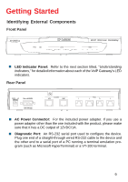
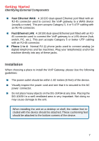
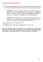
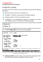
Configuration Configuring the VoIP Gateway There are two ways to configure the VoIP gateway: „ Using a terminal or computer running terminal emulation software connected to the diagnostic port via an RS-232 cable. In the discussion below, the terminal (or computer) is referred to as a console and the connection, a console connection. „ Using a web browser on a computer connected to the device via the WAN or LAN Ethernet connections. In the discussion below, the computer running the browser is referred to as the management station. Configuring the VoIP Gateway Using a Console Setting up a Console First-time configuration can be carried out through a "console," that is, either (a) a VT100-type serial data terminal, or (b) a computer running communications software set to emulate a VT100. The console must be connected to the Diagnostics port. This is an RS-232 port with a 9-socket D-shell connector and DCE-type wiring. Make the connection as follows: 1. Obtain suitable cabling for the connection. You can use either (a) a "null-modem" RS-232 cable or (b) an ordinary RS232 cable and a null-modem adapter. One end of the cable (or cable/adapter combination) must have a 9-pin D-shell connector suitable for the Diagnostics port; the other end must have a connector suitable for the console's serial communications port. 2. Power down the devices, attach the cable (or cable/adapter combination) to the correct ports, and restore power. 3. Set the console to use the following communication parameters for your terminal: „ 9600 baud „ VT-100/ANSI compatible „ No parity checking (sometimes referred to as "no parity") 11
-
 1
1 -
2
-
3
-
4
-
5
-
 6
6 -
 7
7 -
 8
8 -
 9
9 -
 10
10 -
 11
11 -
 12
12 -
 13
13 -
 14
14 -
 15
15 -
 16
16 -
17
-
18
-
19
-
20
-
21
-
22
-
23
-
24
-
25
-
26
-
27
-
28
-
29
-
30
-
31
-
32
-
33
-
34
-
35
-
36
-
37
-
38
-
39
-
40
-
41
-
42
-
43
-
44
-
45
-
46
-
47
-
48
-
49
-
50
-
51
-
52
-
53
-
54
-
55
-
56
-
57
-
58
-
59
-
60
-
61
-
62
-
63
-
64
-
65
-
66
-
67
-
68
-
69
-
70
-
71
-
72
-
73
-
74
-
75
-
76
-
77
-
78
-
79
-
80
-
81
-
82
-
83
 |
 |
