D-Link DXS-3400 Quick Install Guide - Page 12
LED Indicators, Located on the front panel of the Switch are LED indicators: Stack ID, Power1, MGMT - d link 24tc
 |
View all D-Link DXS-3400 manuals
Add to My Manuals
Save this manual to your list of manuals |
Page 12 highlights
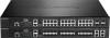
DXS-3400 Series Lite Layer 3 Stackable 10GbE Managed Switch Hardware Installation Guide LED Indicators Located on the front panel of the Switch are LED indicators: Stack ID, Power1, Power2, MGMT, Console, Fan1, Fan2, Fan3, and USB. For each port there is a light representing the port speed and activity. Figure 1-3 LED indicators for the DXS-3400-24TC LED Stack ID Power 1, Power 2 Management (MGMT) Console Figure 1-4 LED indicators for the DXS-3400-24SC Description This 7-segment LED can display numbers from 1 to 4 and the following letters H, h, E, and G. The stacking ID (1 to 4) can be assigned manually by the user or automatically by the system. The letter 'H' will be displayed if this switch is the master switch in the stack. The letter 'h' will be displayed if this switch is the backup master switch in the stack. The letter 'E' will be displayed if there was an error in the system's self-test. The letter 'G' will be displayed when the Safeguard engine entered the exhausted mode. This LED will light solid green after the Switch has been powered on successfully. This LED will light solid amber if the Switch's power supply fails. This LED will be off when the Switch is no longer receiving power (i.e. powered off). This LED will light solid green after a link to the management port was successfully established. This LED will blink when activity on this port is taking place. This LED will be off when there is no link present or when this interface was shut down from within the Switch's configuration. This LED will light solid green when the RJ45 console port is active. The LED will light solid amber when the mini-USB console port is active. 12
-
 1
1 -
2
-
3
-
4
-
5
-
6
-
 7
7 -
 8
8 -
 9
9 -
 10
10 -
 11
11 -
 12
12 -
 13
13 -
 14
14 -
 15
15 -
 16
16 -
 17
17 -
18
-
19
-
20
-
21
-
22
-
23
-
24
-
25
-
26
-
27
-
28
-
29
-
30
-
31
-
32
-
33
-
34
-
35
-
36
-
37
-
38
-
39
-
40
-
41
-
42
-
43
-
44
-
45
-
46
-
47
-
48
-
49
-
50
-
51
-
52
-
53
-
54
-
55
-
56
-
57
-
58
-
59
-
60
 |
 |
