D-Link DXS-3400 Quick Install Guide - Page 14
Power Supply Module, Fan Module, Component, Description
 |
View all D-Link DXS-3400 manuals
Add to My Manuals
Save this manual to your list of manuals |
Page 14 highlights
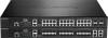
DXS-3400 Series Lite Layer 3 Stackable 10GbE Managed Switch Hardware Installation Guide Figure 1-8 Rear Panel view of the DXS-3400-24SC with a DC Power Supply Components that can be found on the rear panel of this switch are listed in the table below. Component Description Security Lock Provide a Kensington-compatible security lock to be able to connect to a secure immovable device. Insert the lock into the notch and turn the key to secure the lock. The lock-and-cable apparatus should be purchased separately. Switch GND Use an electrical grounding wire and connect one end of the wire to the Switch GND and the other end of the wire to an electrical grounding point most commonly found on the Switch mounting rack itself. Three Fan Module Slots Two Power Supply Module Slots These slots can be equipped with the following fan module. DXS-FAN100 (Normal fan tray with front-to-back airflow) These slots can be equipped with the following additional power modules. Only one power supply module is included. Any additional modules should be bought separately. DXS-PWR300AC (300 Watt AC power supply tray with front-to-back airflow) DXS-PWR300DC (300 Watt DC power supply tray with front-to-back airflow) Power Supply Module Connect the one end of the AC power cord supplied to the AC power connector and the other end into a properly grounded electrical outlet. The Switch will automatically adjust the power setting to adapt to any voltage supply in the range from 100~240 VAC at 50~60 Hz. In addition, an optional second power supply module can be plugged into the second power supply connector slot. The primary and secondary power supply can be either AC supplied or DC supplied, depending on the power supply module inserted. This makes it dual redundant. Fan Module The fan modules on the Switch provide front-to-back airflow and are hot-swappable. The Switch also includes smart fans that will automatically change their speed depending on the internal temperature detected by the sensors built-in the hardware. These smart fans support two states. They can either running at a low speed, or running at a high speed. The following will explain when these fans will toggle between low and high speeds: DXS-3400-24TC: When the internal temperature, detected by the sensor, rises above 37 °C, the fan will automatically change to the high speed. When the internal temperature, detected by the sensor, falls below 33 °C, the fan will automatically change to the low speed. DXS-3400-24SC: When the internal temperature, detected by the sensor, rises above 39 °C, the fan will automatically change to the high speed. When the internal temperature, detected by the sensor, falls below 36 °C, the fan will automatically change to the low speed. 14
-
 1
1 -
2
-
3
-
4
-
5
-
6
-
7
-
8
-
 9
9 -
 10
10 -
 11
11 -
 12
12 -
 13
13 -
 14
14 -
 15
15 -
 16
16 -
 17
17 -
 18
18 -
 19
19 -
20
-
21
-
22
-
23
-
24
-
25
-
26
-
27
-
28
-
29
-
30
-
31
-
32
-
33
-
34
-
35
-
36
-
37
-
38
-
39
-
40
-
41
-
42
-
43
-
44
-
45
-
46
-
47
-
48
-
49
-
50
-
51
-
52
-
53
-
54
-
55
-
56
-
57
-
58
-
59
-
60
 |
 |
