D-Link DXS-3400 Quick Install Guide - Page 13
Rear Panel Components, Fan1, Port LEDs, LED Indicators, Appendix A - Technical Specifications - 24sc d link
 |
View all D-Link DXS-3400 manuals
Add to My Manuals
Save this manual to your list of manuals |
Page 13 highlights
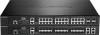
DXS-3400 Series Lite Layer 3 Stackable 10GbE Managed Switch Hardware Installation Guide LED Description This LED will be off when both console ports are not active. Fan1, Fan2, Fan3 This LED will light solid green when the fan is operating normally. This LED will light solid amber when the Switch is booting up or when a diagnostics test is taking place. This LED will blink amber when a fan fails. This LED will be off when the fan is not receiving power. USB Port LEDs This LED will light solid green if a USB flash drive is plugged in. This LED will blink green when the Switch is reading or writing data to and from the USB drive. This LED will be off when no USB drive is plugged into the USB port. This LED will light solid red when a USB drive failure has been detected. This LED will light solid green when there is a connection to a 10 Gbps Ethernet device on any of the ports. This LED will light solid amber when there is a connection to a 100/1000 Mbps Ethernet device on any of the RJ45 ports. This LED will light solid amber when there is a connection to a 1 Gbps Ethernet device on any of the SFP+ fiber ports. This LED will blink when a port is active. This LED will be off when there is no link or activity. Refer to the LED Indicators section in the Appendix A - Technical Specifications for more LED information. Rear Panel Components The rear panel of the Switches in this series features a security lock, a GND, power supply module slots, and fan module slots. One AC power supply module and three fan modules are included in the package for the Switch. Any additional power supply module needs to be bought separately. This switch also supports the use of a DC power supply module. Figure 1-5 Rear panel view of the DXS-3400-24TC with an AC Power Supply Figure 1-6 Rear Panel view of the DXS-3400-24TC with a DC Power Supply Figure 1-7 Rear panel view of the DXS-3400-24SC with a AC Power Supply 13
-
 1
1 -
2
-
3
-
4
-
5
-
6
-
7
-
 8
8 -
 9
9 -
 10
10 -
 11
11 -
 12
12 -
 13
13 -
 14
14 -
 15
15 -
 16
16 -
 17
17 -
 18
18 -
19
-
20
-
21
-
22
-
23
-
24
-
25
-
26
-
27
-
28
-
29
-
30
-
31
-
32
-
33
-
34
-
35
-
36
-
37
-
38
-
39
-
40
-
41
-
42
-
43
-
44
-
45
-
46
-
47
-
48
-
49
-
50
-
51
-
52
-
53
-
54
-
55
-
56
-
57
-
58
-
59
-
60
 |
 |
