Dell Alienware M11x R3 Service Manual - Page 29
Replacing the Status Light Board
 |
View all Dell Alienware M11x R3 manuals
Add to My Manuals
Save this manual to your list of manuals |
Page 29 highlights
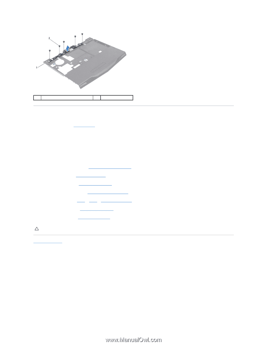
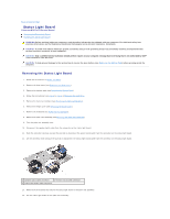
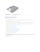
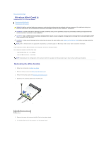
1 status light board 2 screws (5) Replacing the Status Light Board 1. Follow the instructions in Before You Begin. 2. Place the status light board on the palm rest assembly and replace the five screws that secure the status light board to the palm rest assembly. 3. Connect the speaker lights cable to the connector on the status light board. 4. Insert the status light board cable into the connector on the status light board and press the connector latch into the connector to secure the cable. 5. Insert the power board cable into the connector on the status light board and press down on the connector latch to secure the cable. 6. Replace the palm rest assembly (see Replacing the Palm Rest Assembly). 7. Replace the keyboard (see Replacing the Keyboard). 8. Replace the hinge cover (see Replacing the Hinge Cover). 9. Replace the memory module(s) (see Replacing the Memory Module(s)). 10. Follow the instructions from step 6 to step 8 in Replacing the Hard Drive. 11. Replace the battery pack (see Replacing the Battery Pack). 12. Replace the base cover (see Replacing the Base Cover). CAUTION: Before turning on the computer, replace all screws and ensure that no stray screws remain inside the computer. Failure to do so may result in damage to the computer. Back to Contents Page
-
 1
1 -
2
-
3
-
4
-
5
-
6
-
7
-
8
-
9
-
10
-
11
-
12
-
13
-
14
-
15
-
16
-
17
-
18
-
19
-
20
-
21
-
22
-
23
-
 24
24 -
 25
25 -
 26
26 -
 27
27 -
 28
28 -
 29
29 -
 30
30 -
 31
31 -
 32
32 -
 33
33 -
 34
34 -
35
-
36
-
37
-
38
-
39
-
40
-
41
-
42
 |
 |